Wooden raised beds · Guide 25
How to Build a 4x4 Cedar Raised Garden Bed
Build a low, open-bottom cedar bed with a clear cut list, visible corner joints, a checked soil quantity, and room to garden from all four sides.
01 / See the shape
View the project
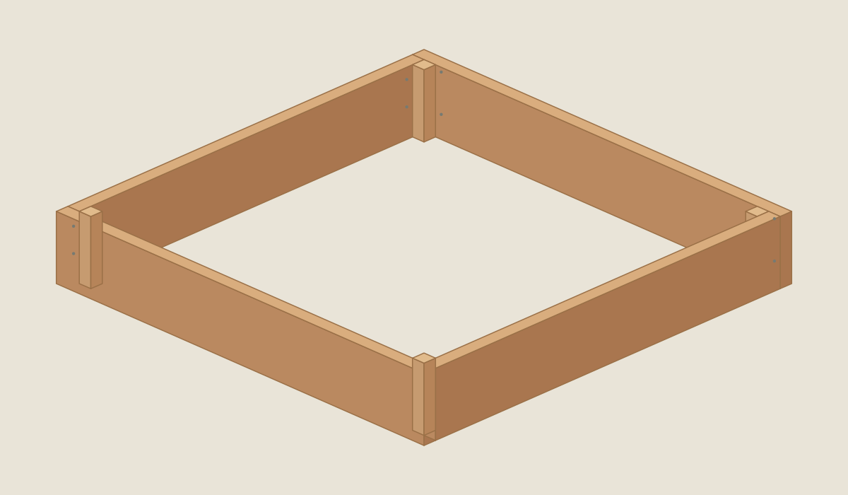
Loading the 3D view…
Drag to turn. Pinch or use + / − to zoom. The written step covers workholding and tool use.
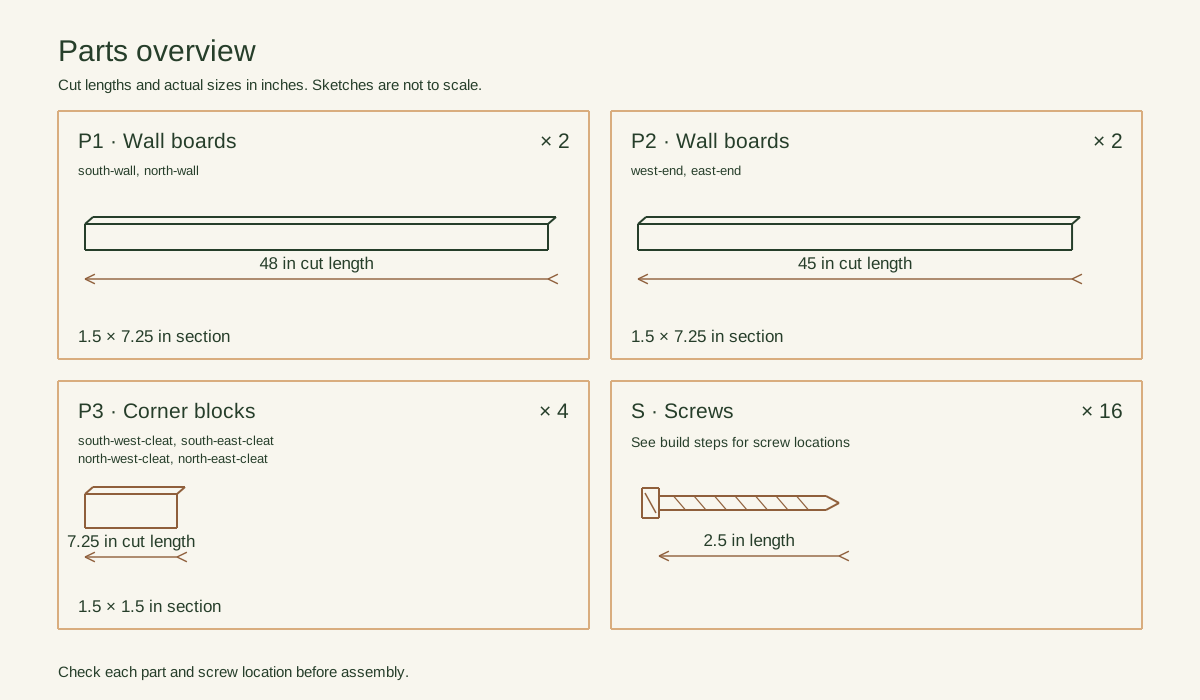
Scroll or swipe the enlarged drawing to read its dimensions. Choose Fit to see the whole drawing again.
Low square cedar bed. Check the dimensions and build steps before cutting.
02 / Plan your build
Before you start
A first raised bed can be a simple wooden edge around suitable garden soil. This version uses four cedar walls and four short corner blocks. There is no floor to drain, no elevated base to support, and no hidden frame to repair. The corners remain visible until filling, so the important checks happen while the work is still accessible.
Choose a level area of suitable native garden soil, with room to reach from all four sides. Do not place this bed on paving, a deck, roof, wall edge, or slope. Its open bottom does not separate plant roots from contaminated soil below. OSU Extension discusses matching bed width to reach and assessing soil and access; those principles do not approve this original corner connection.
Where it goes
Firm, level native garden soil with room to reach in from all four sides. Not for paving, a deck, a roof, a wall edge, or a slope. The open bottom does not separate roots from contaminated soil below.
Footprint: 48 × 48 inches (16 square feet). Leave room to reach in from all four sides.
What to expect
Accurate square cuts, clamped drilling, and careful site assessment. Plan 3–5 hands-on hours.
A planning estimate for the hands-on work, once the materials are bought and the tools are set up. It has not been timed on a finished build.
Check the spot
- Firm, level native garden soil with room to reach in from all four sides. Not for paving, a deck, a roof, a wall edge, or a slope. The open bottom does not separate roots from contaminated soil below.
- Measure the boards and hardware you actually bought before you cut, and set up a steady work surface. Keep other people back while you cut and drill.
Stop and check first if…
- Stop before ground disturbance when buried services, private irrigation, major roots, or past soil contamination are unresolved.
- Do not use this low frame on paving, a deck, a roof, a wall edge, or a slope, and do not raise a downhill wall or add fill against a building to fix a poor site.
- Stop if the selected fastener instructions or measured wood sections do not fit the corner detail.
- Do not move the frame once it is filled. The soil figures are volumes, not a wet-load rating.
- No glue substitutes for a failed or split joint: stop and replace the part.
Work safely
- Have a tape, square, pencil, straightedge, level, suitable clamps, a saw with supported work, drill/driver, the selected screw's specified bits, countersink where appropriate, abrasive paper, and safe soil-handling containers. Match eye, hearing, dust, and handling protection to the actual tools and material. Clamp work for drilling and keep short blocks out of a freehand cutting setup; a caught drill can spin an unsecured part.
- Mark a 48-inch square and confirm reach from every side. Preserve required access and existing safe drainage. Identify roots, irrigation, utilities, and prior land use before disturbing the ground. Use current applicable utility-location procedures and account for privately owned lines. No excavation permission or local exemption is issued by this guide.
- Stop for uncertain utilities, major roots, contamination concerns, unstable or sloping ground, persistent ponding, a frame that will not sit flat, unsuitable stock, or a screw manufacturer's requirements that cannot be met by the corner. Do not solve a poor site by raising a downhill wall, trapping runoff, or adding fill against a building.
- Stop before ground disturbance when buried services, private irrigation, major roots, or past soil contamination are unresolved.
- Do not use this low frame on paving, a deck, a roof, a wall edge, or a slope, and do not raise a downhill wall or add fill against a building to fix a poor site.
- Stop if the selected fastener instructions or measured wood sections do not fit the corner detail.
- Do not move the frame once it is filled. The soil figures are volumes, not a wet-load rating.
- No glue substitutes for a failed or split joint: stop and replace the part.
Budget
We have not put a price on this one yet. Lumber and hardware prices change by store and season, so price the list under What you need at your local supplier before you buy.
03 / Gather and cut
What you need
Cedar wall boards
2 boards
Surfaced untreated cedar 2 × 8; actual 1.5 × 7.25 inches. Two 8-foot boards with sound usable ends.
Cut one 48-inch L and one 45-inch E from each board. At 1/8-inch kerf, each pair uses 93.25 inches before initial end trimming.
Cedar corner stock
1 length
Surfaced untreated cedar 2 × 2; actual 1.5-inch-square section. One 8-foot length, or a shorter verified piece supplying all four blocks.
Four 7.25-inch C blocks plus four 1/8-inch kerfs require 29.5 inches before end trimming.
Corner screws
16 installed; 4 spare screws
Proposed #8 × 2.5-inch stainless outdoor wood screws; confirm the exact maker's cedar, pilot, and spacing instructions. Package with at least 20 matching screws.
Two per face at each corner. Follow the screw maker’s pilot and spacing instructions; spare screws are not extra installed fasteners.
Raised-bed growing medium
5 bags
Selected raised-bed mix suited to the plants and assessed native soil below. Five 1.5-cubic-foot bags, or an equivalent measured supply.
This bed needs 7.2917 cubic feet at the 6.25-inch fill line; 7.5 cubic feet leaves about 0.2083 cubic foot before settlement. Do not fill the freeboard.
Cut list
| Piece | How many | Cut length | Note |
|---|---|---|---|
| L — Long wall | 2 | 48 in | Part L, cut from surfaced untreated cedar 2x8. Size: 48 × 7.25 × 1.5 in. Check the plan sheets for its reference edges and any shaped detail. |
| E — End wall | 2 | 45 in | Part E, cut from surfaced untreated cedar 2x8. Size: 45 × 7.25 × 1.5 in. Check the plan sheets for its reference edges and any shaped detail. |
| C — Internal corner block | 4 | 7.25 in | Part C, cut from surfaced untreated cedar 2x2. Size: 7.25 × 1.5 × 1.5 in. Check the plan sheets for its reference edges and any shaped detail. |
Tools
- Tape or rule, square, and pencil
- Clamps and stable supported work surface
- Suitable saw with its required guarding
- Drill/driver, selected-product pilot and clearance bits, and countersink
- Abrasives for hand-contact edges
- Level and straightedge
- Hand tools and a receiving container for the assessed soil work
Protective gear
- Eye protection for cutting and drilling; match other protection to the actual tool instructions.
- Appropriate hearing protection and wood-dust control for the selected cutting method.
04 / Put it together
Build steps
- 01
Measure and record the stock
Check each wall board at several points: this plan requires 1-1/2-inch thickness and 7-1/4-inch height. Check 1-1/2-inch-square corner stock. Write down usable lengths after damaged ends are excluded. Different actual stock requires a reconciled design, not an unrecorded adjustment at one corner.
Close-up · Whole model shows the complete part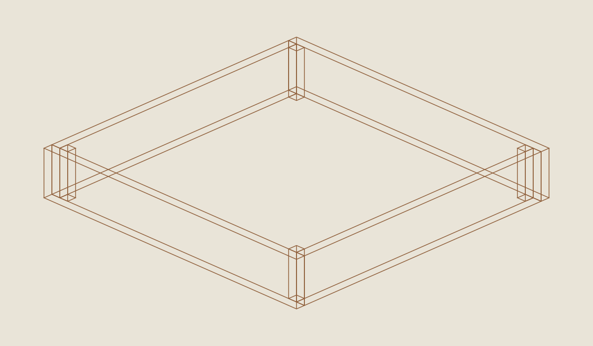
Loading the 3D view…
Drag to turn. Pinch or use + / − to zoom. The written step covers workholding and tool use.
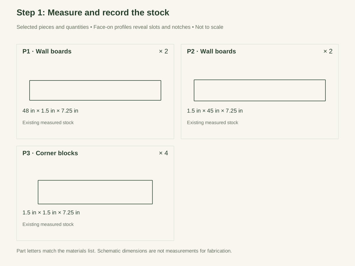
Scroll or swipe the enlarged drawing to read its dimensions. Choose Fit to see the whole drawing again.
Check: Record wall stock at 1.5 × 7.25 inches and corner stock at 1.5 × 1.5 inches; reject split or twisted pieces.
- 02
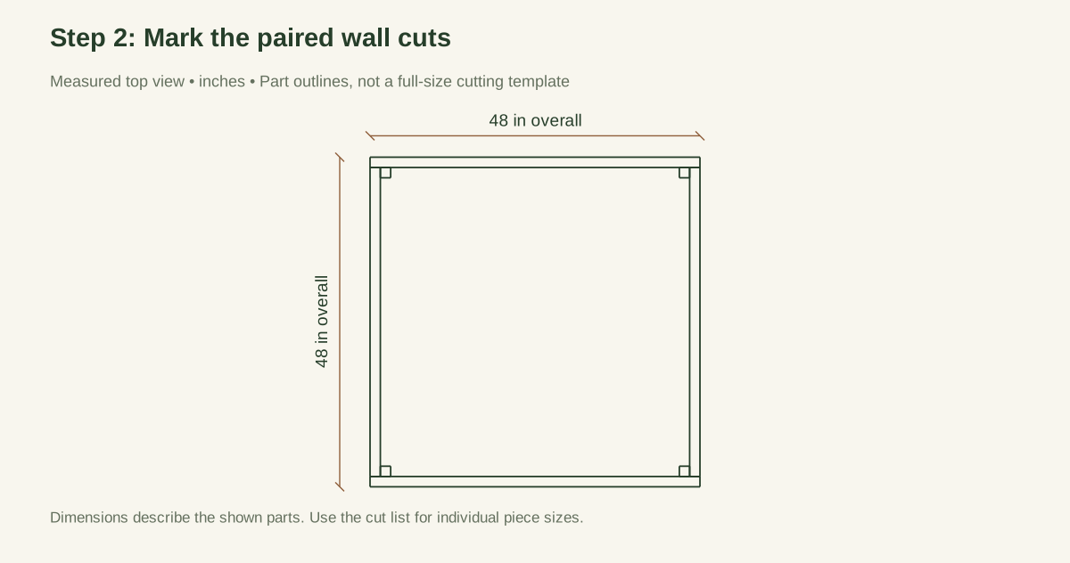
Mark the paired wall cuts
From a square datum end on each wall board, mark one 48-inch L and one 45-inch E, leaving the saw kerf on the waste side of each finished line. Mark the four 7-1/4-inch blocks on the corner stock. Label inside faces and bottoms before pieces can be confused.
Close-up · Whole model shows the complete part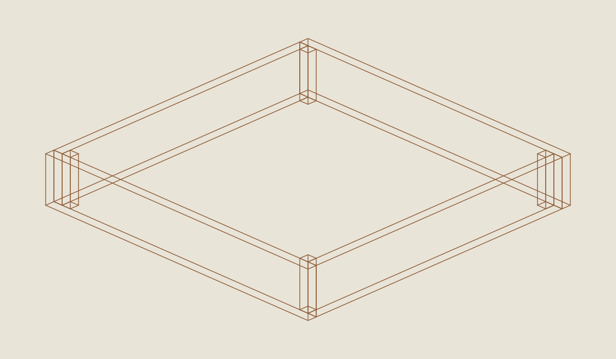
Loading the 3D view…
Drag to turn. Pinch or use + / − to zoom. The written step covers workholding and tool use.
Scroll or swipe the enlarged drawing to read its dimensions. Choose Fit to see the whole drawing again.
Check: One 48-inch side and one 45-inch end come from each wall board, with kerf and end trimming allowed.
- 03
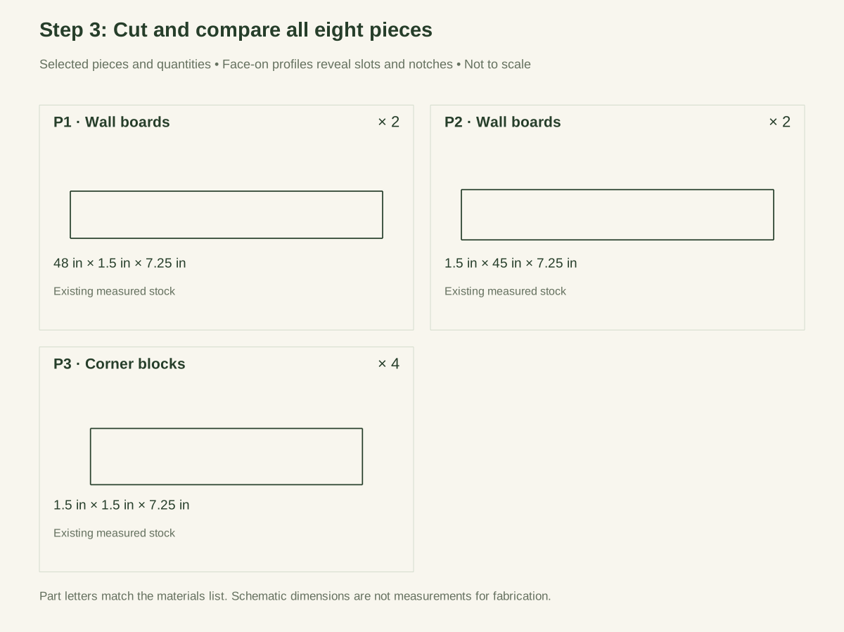
Cut and compare all eight pieces
Support and clamp the stock as required by the tool. Cut square ends without trapping an offcut. Compare each like pair face to face; a proposed shop target is matching lengths within 1/32 inch. Check blocks against the actual wall height. Remove splinters but retain flat mating surfaces.
Close-up · Whole model shows the complete part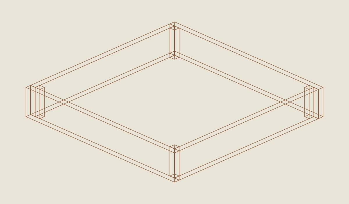
Loading the 3D view…
Drag to turn. Pinch or use + / − to zoom. The written step covers workholding and tool use.
Scroll or swipe the enlarged drawing to read its dimensions. Choose Fit to see the whole drawing again.
Check: Four walls and four blocks are cut; like parts match without forcing.
- 04
Fit and square the empty frame
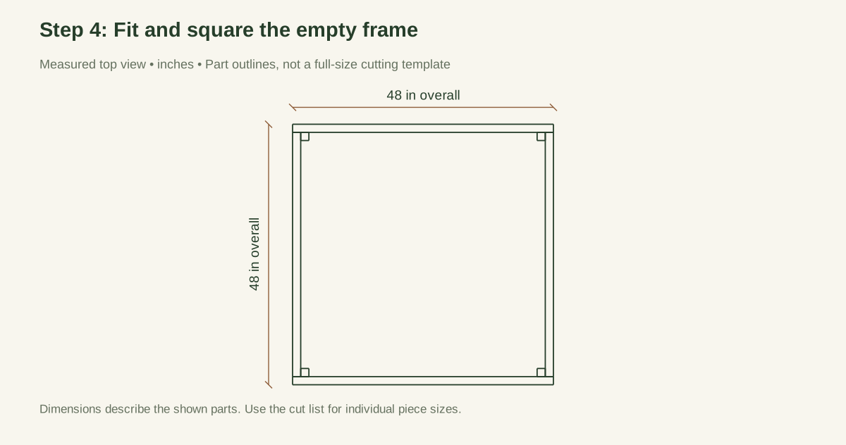
Place L pieces outside E, on a flat working surface. Put one C block in each inside corner, flush at both top and bottom. Clamp the joints before fastening. Check 48 inches on every outside side and a 45-inch-square inner rectangle before the block intrusions.
Measure the two outside diagonals: the design value is 48 × sqrt(2) = 67.8823 inches. Aim for a difference no greater than 1/8 inch as the proposed assembly target. Do not force twisted boards into temporary square and assume they will remain so after the clamps come off.
Close-up · Whole model shows the complete part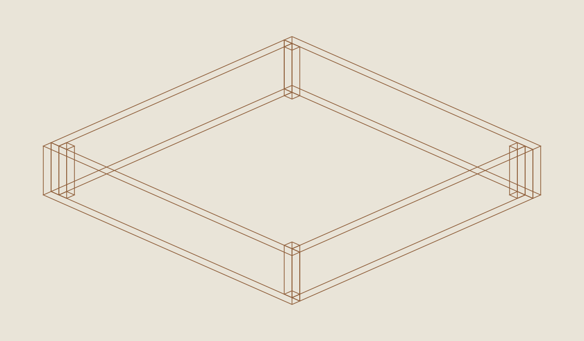
Loading the 3D view…
Drag to turn. Pinch or use + / − to zoom. The written step covers workholding and tool use.
Scroll or swipe the enlarged drawing to read its dimensions. Choose Fit to see the whole drawing again.
Check: Outside dimensions are 48 × 48 inches; compare both diagonals to approximately 67.882 inches.
- 05
Mark the exact existing screw pattern
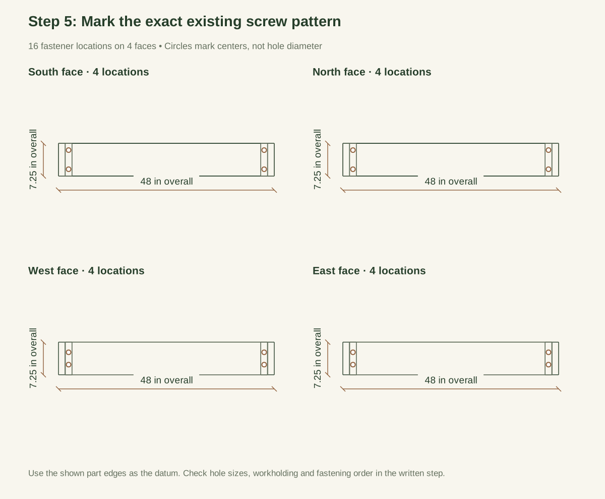
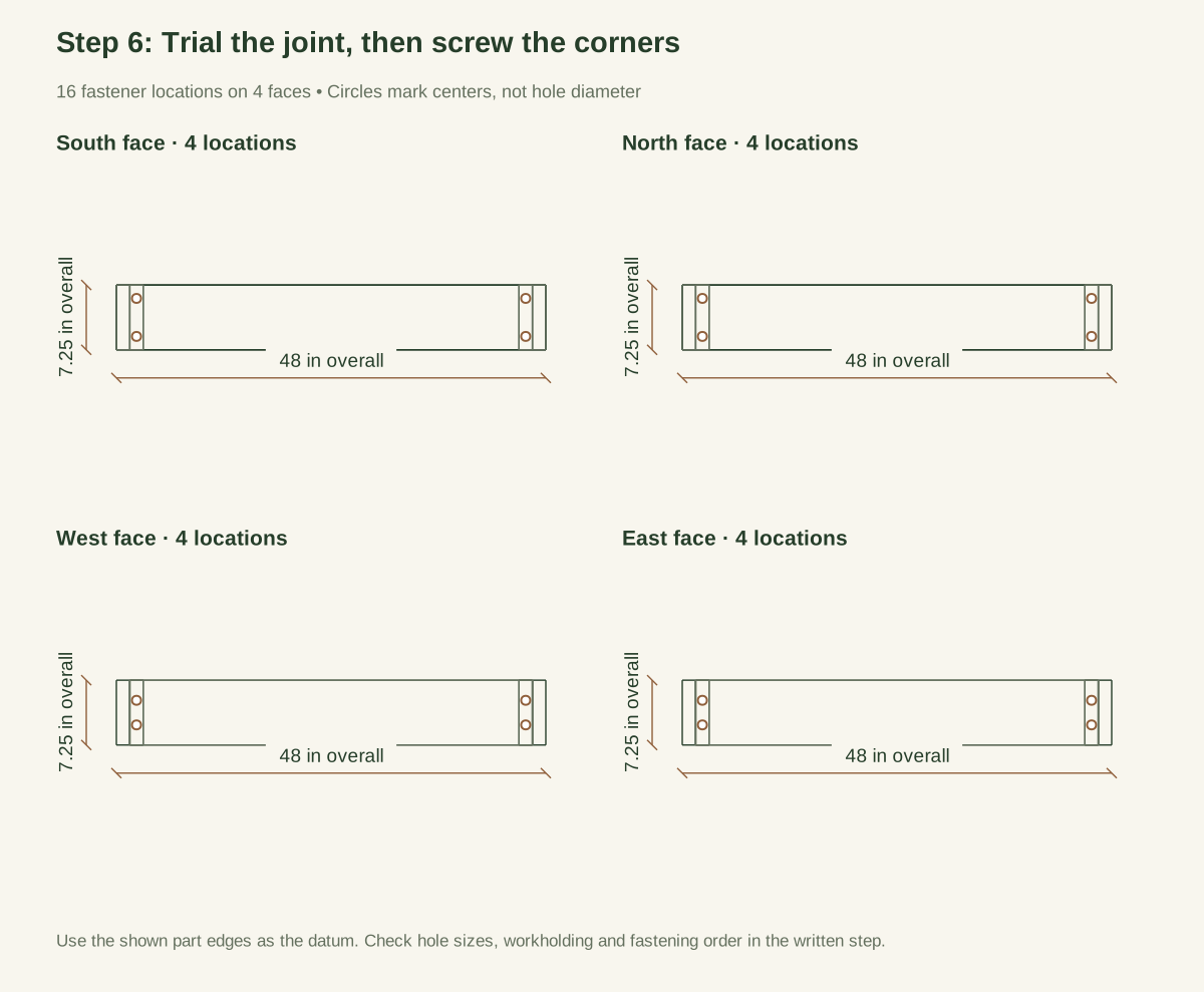
Use the bottom edge of every wall as the height datum. On each L wall, the screw lines are 2-1/4 inches from its ends, with holes at 1-1/2 and 5-3/4 inches above the bottom. On each E wall, the lines are 3/4 inch from its ends, with holes at 2-1/4 and 5 inches above the bottom.
These heights deliberately stagger the perpendicular screws entering the same corner block. Four corners × two wall faces × two screws = sixteen screws.
Close-up · Whole model shows the complete part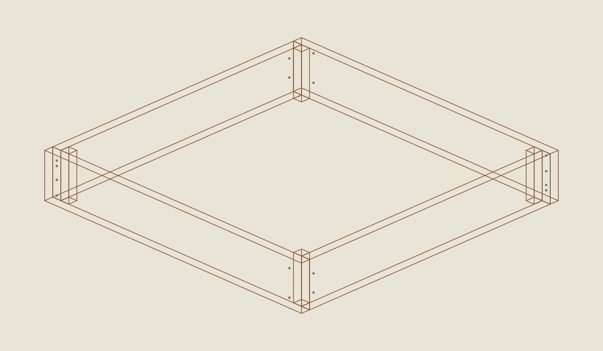
Loading the 3D view…
Drag to turn. Pinch or use + / − to zoom. The written step covers workholding and tool use.
Scroll or swipe the enlarged drawing to read its dimensions. Choose Fit to see the whole drawing again.
Check: Long-wall holes are 2.25 inches from the ends at heights 1.5 and 5.75; end-wall holes are 0.75 from the ends at heights 2.25 and 5.
- 06
Trial the joint, then screw the corners
Use the selected screw manufacturer's pilot, clearance, countersink, and edge-distance requirements. Test the actual cedar and screw in scrap first. Do not treat a generic bit size as a universal cedar pilot. If the requirements do not fit this narrow corner block, stop and get qualified advice on the joint rather than placing a larger screw into a split.
Keep each real corner clamped while drilling. A wall clearance hole, when specified, must not continue as a clearance hole through the receiving block. Use controlled depth and torque; seat the head as directed without crushing the surface. Install the long-wall and staggered end-wall screws while preserving the frame's square. Recheck diagonals partway through and after all sixteen screws are seated. Record the actual fastener and drilling setup.
Close-up · Whole model shows the complete part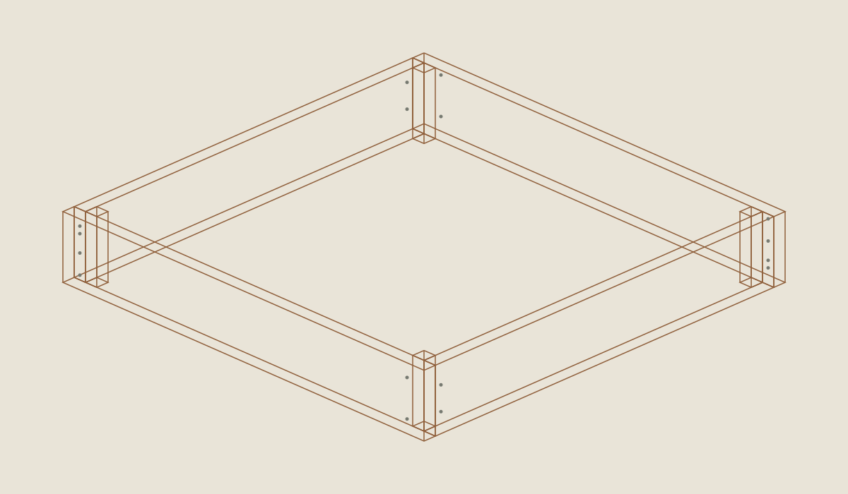
Loading the 3D view…
Drag to turn. Pinch or use + / − to zoom. The written step covers workholding and tool use.
Scroll or swipe the enlarged drawing to read its dimensions. Choose Fit to see the whole drawing again.
Check: Keep every corner clamped; 16 screws are installed with no split block or exposed point.
- 07
Inspect before any connection is covered
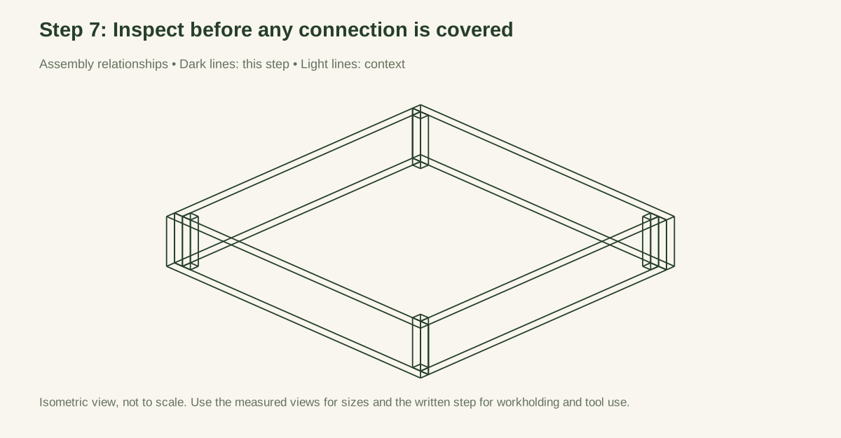
Release clamps and check that corners remain closed and the frame lies flat. Inspect every block for splitting, stripped holes, and projecting points. Ease hand-contact rim edges and use a cloth to find splinters. Inspect and record the corner dimensions while all joints remain visible. A defect found here must be corrected before adding soil pressure.
Close-up · Whole model shows the complete part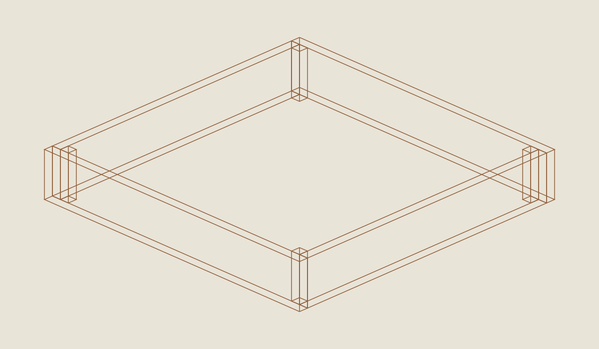
Loading the 3D view…
Drag to turn. Pinch or use + / − to zoom. The written step covers workholding and tool use.
Scroll or swipe the enlarged drawing to read its dimensions. Choose Fit to see the whole drawing again.
Check: Every corner block is free of splits, stripped holes, and projecting screw points, checked while the joints are still visible.
- 08
Position the empty frame on the cleared site
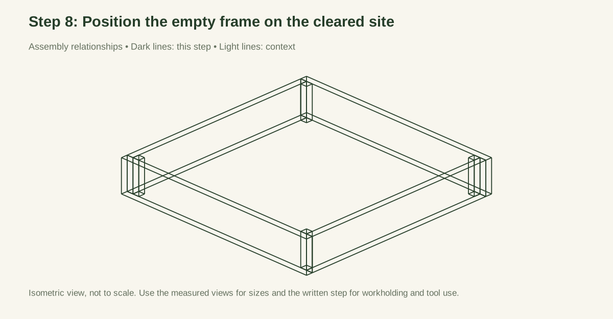
Move the empty assembly with appropriate help, supporting more than one corner. Do not drag it across roots or lift it by a single wall. Set it on suitable level native ground and check contact beneath all four sides. Minor surface preparation stays within the already assessed scope. Significant grading, retaining, drainage redirection, or root disturbance is a separate task, not a finishing step in this plan.
Close-up · Whole model shows the complete part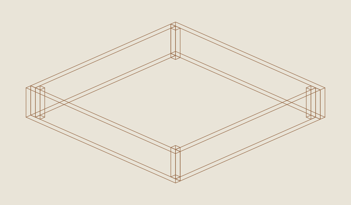
Loading the 3D view…
Drag to turn. Pinch or use + / − to zoom. The written step covers workholding and tool use.
Scroll or swipe the enlarged drawing to read its dimensions. Choose Fit to see the whole drawing again.
Placement reference: the empty frame, not a site or drainage design.
Check: The empty frame bears on suitable cleared soil without rocking or changing the site drainage.
- 09
Mark the fill line and fill gradually
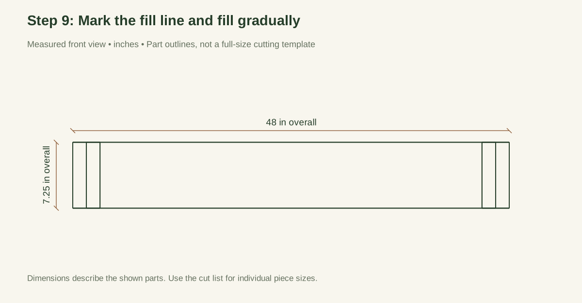
Mark 6-1/4 inches above the prepared ground on the inside walls. Add the selected medium in passes around the bed rather than dumping all bags against one wall. Keep the one-inch freeboard and do not compact the soil by standing on the rim. Stop for a moving corner, an opening joint, unexpected bowing, or a rocking frame. Do not cover a problem by adding the next bag.
Close-up · Whole model shows the complete part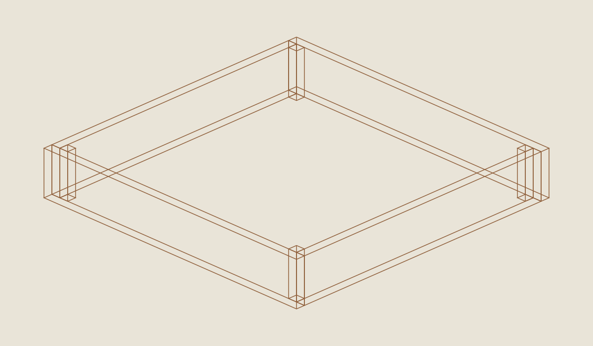
Loading the 3D view…
Drag to turn. Pinch or use + / − to zoom. The written step covers workholding and tool use.
Scroll or swipe the enlarged drawing to read its dimensions. Choose Fit to see the whole drawing again.
Keep the fill below the top edge as described in the step.
Check: The fill line is 6.25 inches above prepared ground, not the 7.25-inch rim.
- 10
Check watering and set up planting
Water in accordance with the selected medium and planting plan. Observe drainage and initial settlement without flooding the site. Check the corners and surface contact again. Use crop-specific spacing and rooting requirements, including the native soil beneath this shallow frame; the four-foot square is not a universal planting grid. Add settled material only to the marked line, not to the top.
Close-up · Whole model shows the complete part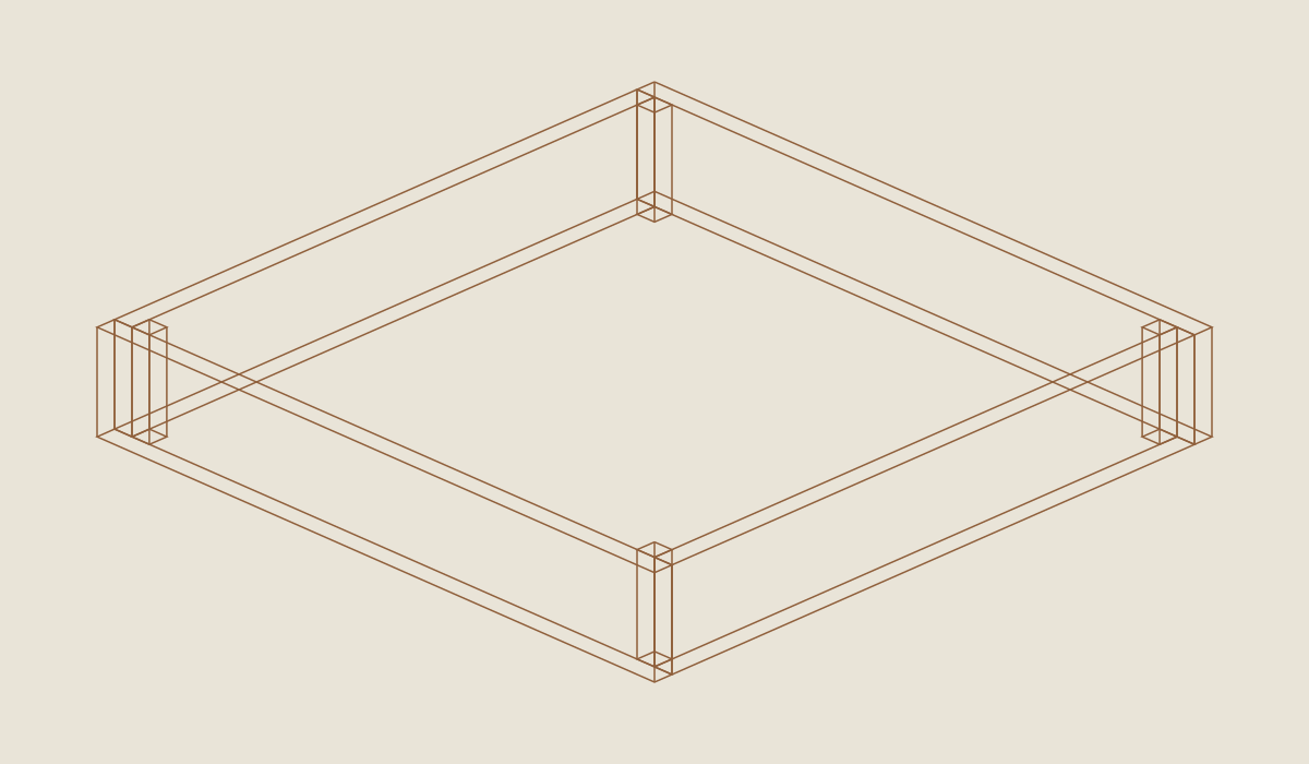
Loading the 3D view…
Drag to turn. Pinch or use + / − to zoom. The written step covers workholding and tool use.
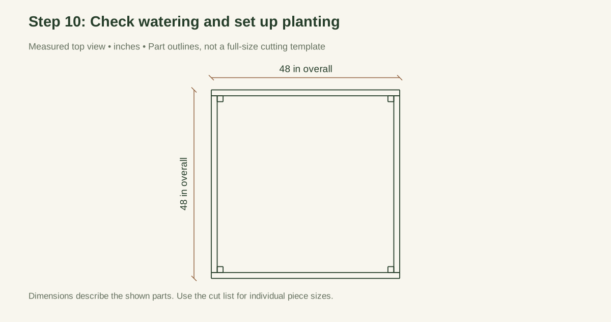
Scroll or swipe the enlarged drawing to read its dimensions. Choose Fit to see the whole drawing again.
Check: Observe drainage and settlement before planting; do not load the walls with pots or people.
05 / Keep it sound
Care
After the build
- Measure the 6.25-inch fill line before adding the selected growing medium; inspect after watering and settlement.
- Space and choose crops by their own spacing and rooting needs, including the native soil under this shallow frame; the four-foot square is not a universal planting grid.
Check it each season
- Inspect after the first watering, substantial rain, and before each planting season. These are recommended triggers, not a demonstrated service interval. Keep pots, seating, and standing loads off the rim. Check screw seating, corner movement, soft wood, and persistent wet areas. Empty the adjacent contents before replacing a wall or block; never remove a loaded side and assume the soil will stay in place.
- Brush accessible dirt off an empty frame, dry replacement parts appropriately, and handle removed wood and hardware under applicable local disposal rules. Do not burn unidentified or coated waste. The project is deliberately simple enough to inspect; adding cladding, a floor, a cover frame, or height changes the design and requires new work.
If something looks wrong
- Frame rocks before filling
- Check: High ground, debris, twisted stock. Fix: Find a suitable flat location or correct the assessed surface; do not wedge it with loose scraps.
- Corner opens while filling
- Check: Split block, stripped hole, unsuitable screw setup. Fix: Stop and unload the affected pressure before repair and renewed review.
- Water remains pooled
- Check: Site, compacted native soil, selected medium. Fix: Stop adding water and reassess; do not drill random wall outlets.
- Cedar softens at the base
- Check: Sustained moisture or deterioration. Fix: Unload locally and replace the complete affected part rather than covering it with trim.
- A source of the specified cedar changes
- Check: Actual section, grade, defects. Fix: Recheck the full cut and joint specification before substituting.
Keep exploring