Wooden raised beds · Guide 37
Build a Lift-Off Garden Pest Screen
A light framed screen that lifts off a matching 4-foot bed for planting and inspection.
01 / See the shape
View the project
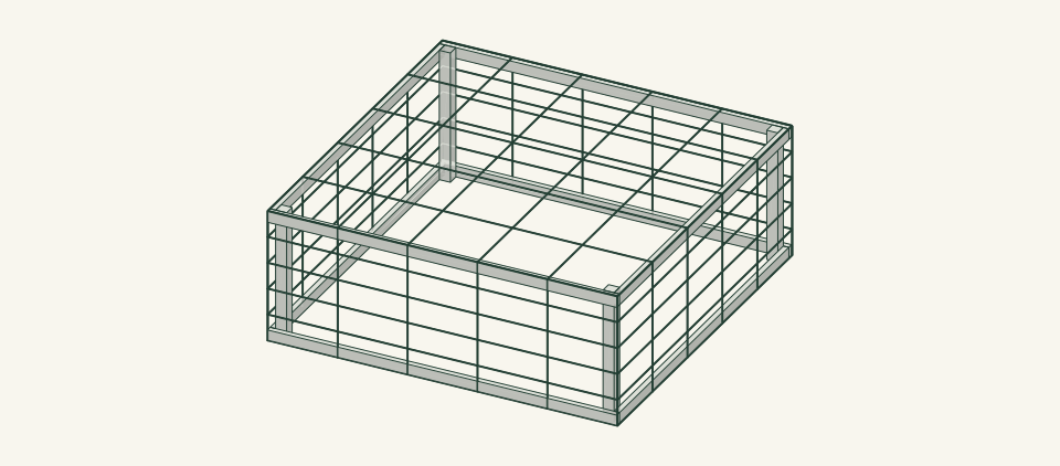
Loading the 3D view…
Drag to turn. Pinch or use + / − to zoom. The written step covers workholding and tool use.
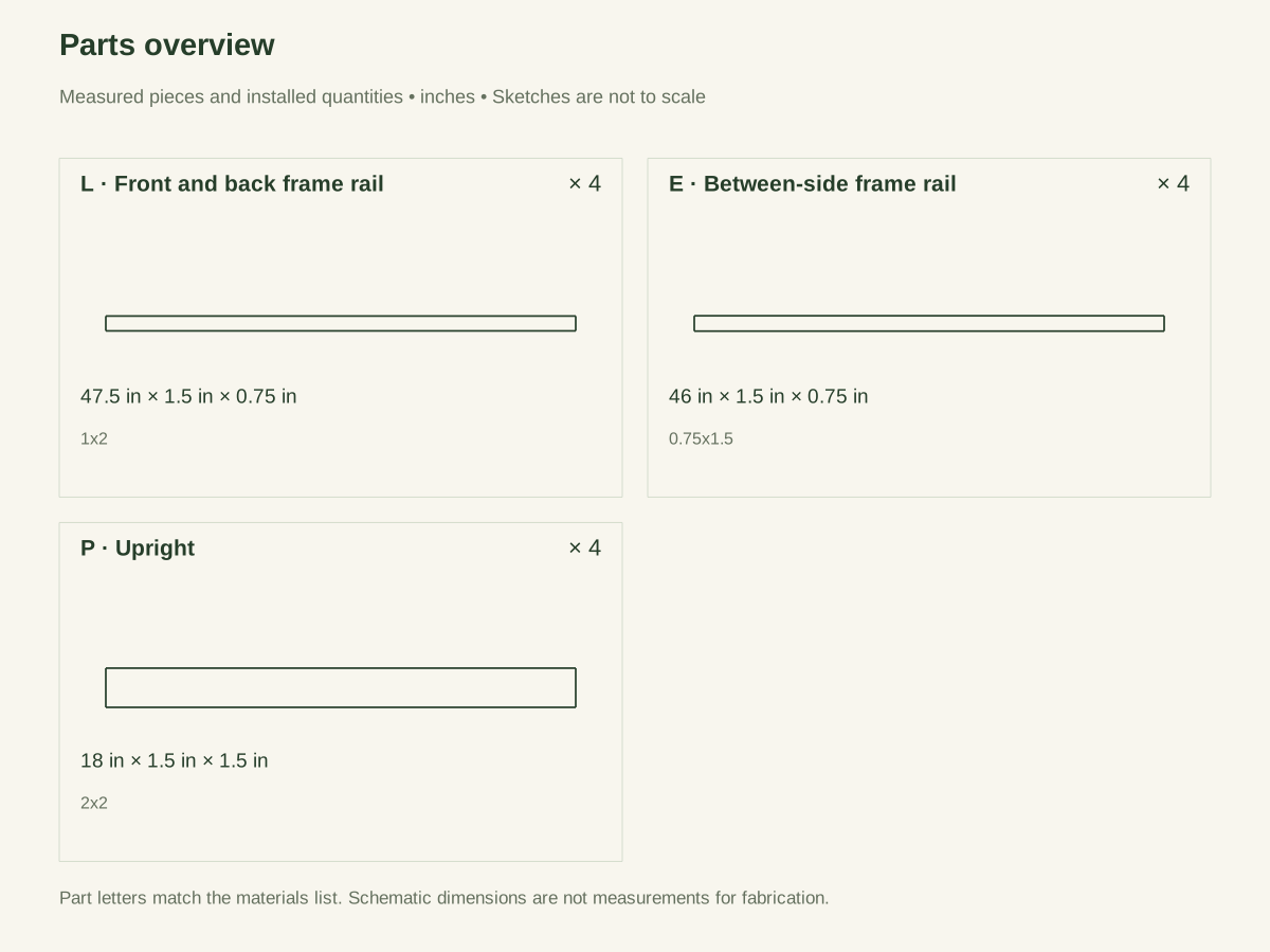
Scroll or swipe the enlarged drawing to read its dimensions. Choose Fit to see the whole drawing again.
Build a Lift-Off Garden Pest Screen. Check the dimensions and build steps before cutting.
02 / Plan your build
Before you start
This removable screen keeps the enclosure separate from the growing bed. Two square frames are joined by short uprights and wrapped with insect mesh. It is a seasonal crop cover, not a wind-rated structure or an animal cage. Select mesh for the actual pest and remove the cover when the crop needs pollinators.
Where it goes
A flat 48 × 48-inch bed rim at least 1.5 inches wide, clear of screw heads; the cover RESTS ON the rim, not around the bed walls. Shelter from wind.
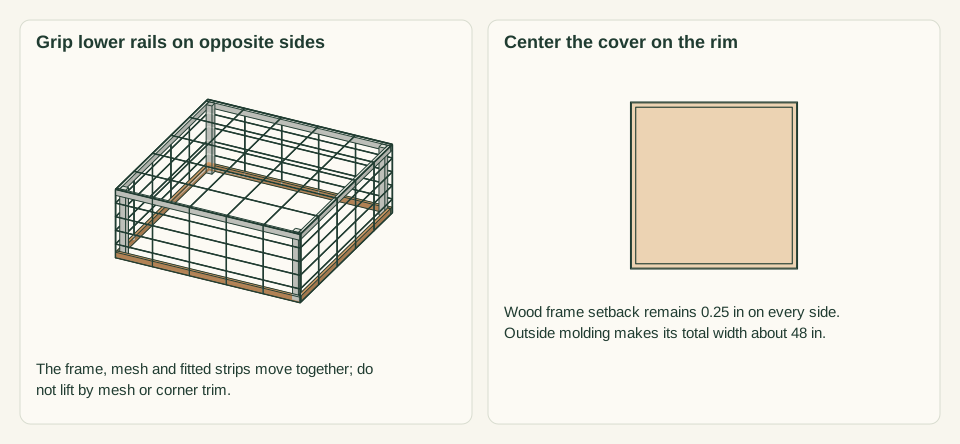
Footprint: 47.5 × 47.5-in wood frame, about 48 × 48 in with molding; allow room around it to work and for two people to lift.
What to expect
Measure accurately, make supported square cuts and drill clamped joints. Plan 4–5 hours including mesh fitting.
A planning estimate for the hands-on work, once the materials are bought and the tools are set up. It has not been timed on a finished build.
Check the spot
- A flat 48 × 48-inch bed rim at least 1.5 inches wide, clear of screw heads; the cover RESTS ON the rim, not around the bed walls. Shelter from wind.
- Measure the usable stock before marking. Keep the assembly area flat and large enough to clamp the work without reaching across a moving cutter.
Stop and check first if…
- Stop if a part splits, a fixing strips, or the assembled object rocks. Unload it before opening a joint.
- Do not substitute an unknown material section or make the object taller or wider without checking every affected part and joint.
Work safely
- Use two people on opposite sides to lift this broad cover. Keep fingers out from under the lower rails while lowering it onto the rim.
- Remove the cover before wind can lift it. Do not add an unplanned ground anchor, climb on it, or use it to hold animals. Fold all mesh edges under strips and inspect for sharp projections.
Budget
We have not put a price on this one yet. Lumber and hardware prices change by store and season, so price the list under What you need at your local supplier before you buy.
03 / Gather and cut
What you need
L — Front and back frame rail
4 pieces
Untreated cedar 1 × 2; actual 0.75 × 1.5 in. Buy four nominal 1 × 2 × 8-ft cedar boards for ALL eight L/E rails. Each board yields one 47.5-in L and one 46-in E, with room for kerf and trimming.
Measure your boards before cutting. Build to the finished sizes written here, not the nominal lumber label.
E — Between-side frame rail
4 pieces
Same 0.75 × 1.5 cedar. Cut from the four boards listed for L; do not buy four extra boards.
Measure your boards before cutting. Build to the finished sizes written here, not the nominal lumber label.
P — Upright
4 pieces
Untreated cedar 2 × 2; actual 1.5 square. One 2 × 2 × 8-ft board.
Measure your boards before cutting. Build to the finished sizes written here, not the nominal lumber label.
M — Insect mesh panels
1 piece
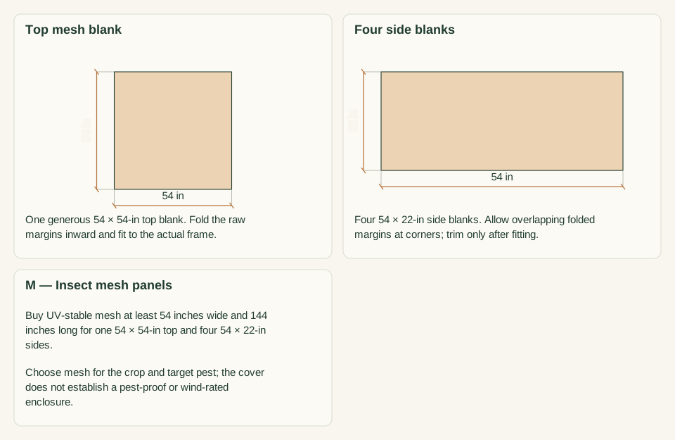
UV-stable insect mesh chosen for the actual pest; mesh is not a load-carrying part. Buy UV-stable mesh at least 54 inches wide and 144 inches long for one 54 × 54-in top and four 54 × 22-in sides.
Fold raw edges inward. Bring side mesh inward over each recessed corner-post face so the vertical strips have solid wood behind them.
HL — Front and rear retaining strip
4 pieces
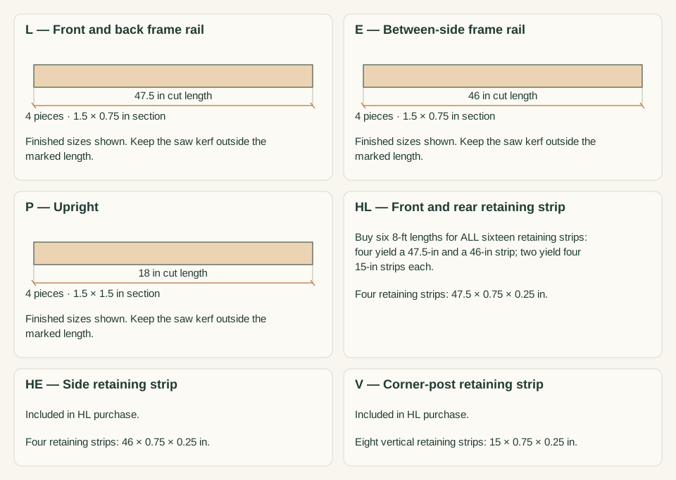
Solid wood screen molding, actual 0.25 × 0.75 in. Buy six 8-ft lengths for ALL sixteen retaining strips: four yield a 47.5-in and a 46-in strip; two yield four 15-in strips each.
Predrill clamped strips to avoid splitting.
HE — Side retaining strip
4 pieces
Same 0.25 × 0.75-in molding. Included in HL purchase.
Fits between the front and rear strips.
V — Corner-post retaining strip
8 pieces
Same 0.25 × 0.75-in molding. Included in HL purchase.
Two per post, on exposed faces between the lower and upper rails.
Frame screws
24 items
#8 × 1.5-in stainless wood screws Buy a pack with at least 24 screws.
Two per long-face overlap and one per end-face overlap. Test pilots in matching scrap.
Retainer screws
80 items
#4 × 0.75-in stainless wood screws Buy a pack with at least 80 screws.
Five per strip; 0.25-in molding leaves 0.5 in into receiving wood.
Cut list
| Piece | How many | Cut length | Note |
|---|---|---|---|
| L — Front and back frame rail | 4 | 47.5 × 1.5 × 0.75 in | Finished length × width × thickness; square ends unless the detail says otherwise. |
| E — Between-side frame rail | 4 | 46 × 1.5 × 0.75 in | Finished length × width × thickness; square ends unless the detail says otherwise. |
| P — Upright | 4 | 18 × 1.5 × 1.5 in | Finished length × width × thickness; square ends unless the detail says otherwise. |
| HL — Front and rear retaining strip | 4 | 47.5 × 0.75 × 0.25 in | Finished length × width × thickness; square ends unless the detail says otherwise. |
| HE — Side retaining strip | 4 | 46 × 0.75 × 0.25 in | Finished length × width × thickness; square ends unless the detail says otherwise. |
| V — Corner-post retaining strip | 8 | 15 × 0.75 × 0.25 in | Finished length × width × thickness; square ends unless the detail says otherwise. |
Tools
- Tape or rule, square and sharp pencil
- Clamps, a flat bench and sacrificial backing
- Suitable guarded saw for the specified stock
- Drill/driver, depth stop and bits matched to the chosen screws
- Fine abrasive and a dust brush
- Scissors for mesh; two people for lifting the assembled cover
Protective gear
- Eye protection during cutting and drilling
- Hearing protection and dust collection appropriate to the actual tools
- Closed footwear; keep loose clothing and gloves away from rotating cutters
04 / Put it together
Build steps
- 01
Check the rim supports the cover
Check the bed is 48 inches square outside with a flat top rim at least 1.5 inches wide. The 47.5-inch wood frame rests ON this rim, centered 0.25 inch inside each bed edge. It does not slide over the walls. Check screws, caps and plants leave this bearing surface clear.
Close-up · Whole model shows the complete part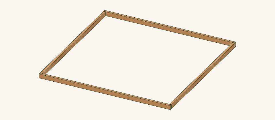
Loading the 3D view…
Drag to turn. Pinch or use + / − to zoom. The written step covers workholding and tool use.
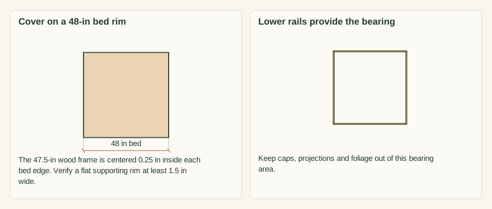
Scroll or swipe the enlarged drawing to read its dimensions. Choose Fit to see the whole drawing again.
The cover rests on top of the bed rim, centered inward. It is not a sleeve that slides around the bed walls.
Check: The lower rails can rest continuously on the flat rim without binding on the bed.
- 02
Cut rails posts and mesh strips
Cut four 47.5-inch L rails, four 46-inch E rails and four 18-inch posts. Cut four 47.5-inch HL strips, four 46-inch HE strips and eight 15-inch V strips. Use actual sections from the list. Label each part and keep kerf outside each cut.
Close-up · Whole model shows the complete part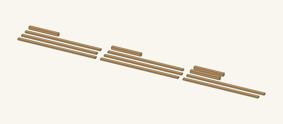
Loading the 3D view…
Drag to turn. Pinch or use + / − to zoom. The written step covers workholding and tool use.
Scroll or swipe the enlarged drawing to read its dimensions. Choose Fit to see the whole drawing again.
Cut the structural rails and posts, then the separately listed mesh-retaining strips. The 3D view shows the structural stock, not hidden future assembly.
Check: Eight rails, four posts and sixteen retaining strips are cut and labeled.
- 03
Clamp the lower square
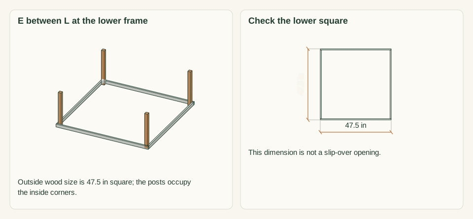
Fit E between L on a flat bench. Place posts inside the four corners with bottoms flush. Clamp rails to posts. Outside wood size is 47.5 inches square; between opposing rail faces it is 46 inches. Posts occupy the inner corners; this is not a slip-over opening.
Close-up · Whole model shows the complete part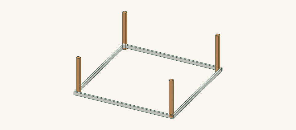
Loading the 3D view…
Drag to turn. Pinch or use + / − to zoom. The written step covers workholding and tool use.
Scroll or swipe the enlarged drawing to read its dimensions. Choose Fit to see the whole drawing again.
Clamp the lower square around the post bottoms. The upper frame has not been fitted.
Check: The lower square is flat and its diagonals match.
- 04
Mark separated corner screw heights
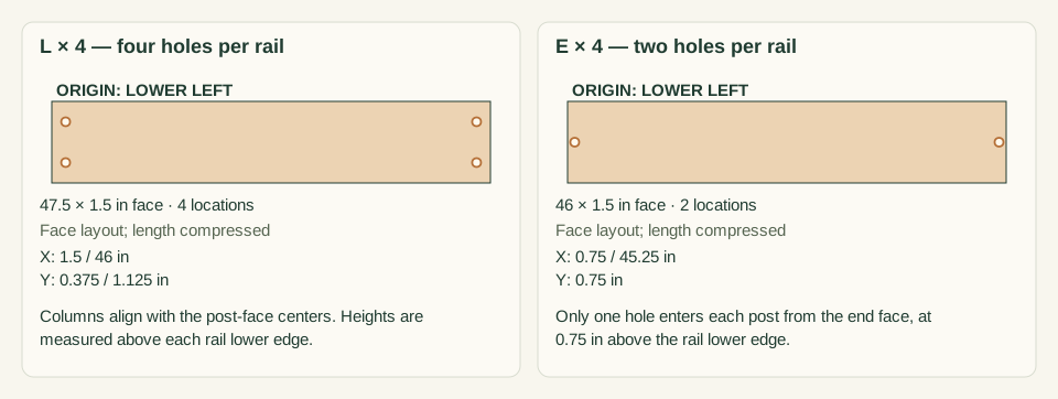
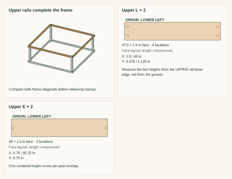
At each long-rail/post overlap mark two holes 0.375 and 1.125 inches above the lower rail edge. On each end-rail/post overlap use ONE hole 0.75 inch above that edge. Center each line across its 1.5-inch post face. Repeat with heights measured from 16.5 inches for the upper rails.
Close-up · Whole model shows the complete part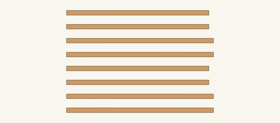
Loading the 3D view…
Drag to turn. Pinch or use + / − to zoom. The written step covers workholding and tool use.
Scroll or swipe the enlarged drawing to read its dimensions. Choose Fit to see the whole drawing again.
Mark the different long-face and end-face patterns on both frames. The unequal heights prevent adjacent screw heads from colliding.
Check: Twelve holes per frame; adjacent screw paths differ in height and heads do not overlap.
- 05
Assemble the lower frame and uprights
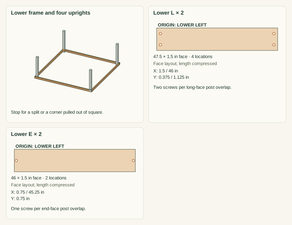
Drill clearance holes through rails only and product-matched pilots into posts. With corners clamped, drive twelve #8 × 1.5-inch lower-frame screws: two per long-face overlap and one per end-face overlap. Stop for splits or a corner pulled out of square.
Close-up · Whole model shows the complete part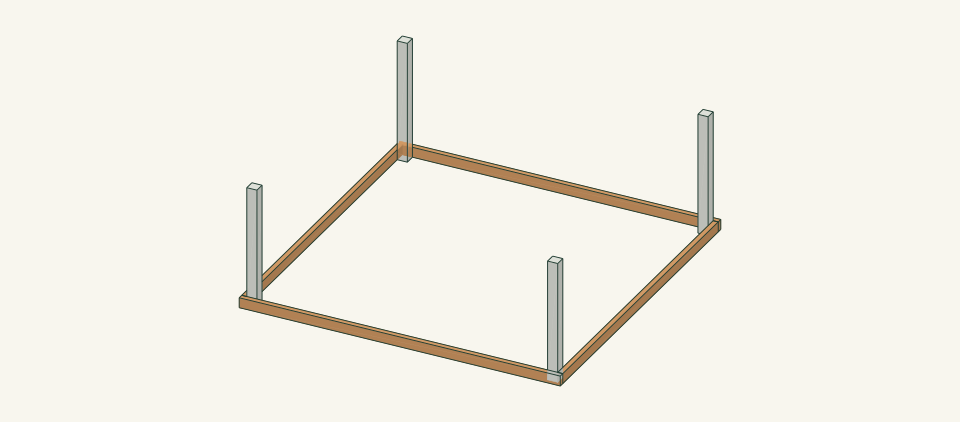
Loading the 3D view…
Drag to turn. Pinch or use + / − to zoom. The written step covers workholding and tool use.
Scroll or swipe the enlarged drawing to read its dimensions. Choose Fit to see the whole drawing again.
Fasten the lower twelve-screw pattern with the corners clamped. The upper rails remain absent.
Check: Four uprights stand parallel and all lower screw heads are flush.
- 06
Fit the upper frame
Clamp the upper rails with their lower edges 16.5 inches above the post bottoms. Repeat the twelve-screw pattern from step 4. Compare both frame diagonals and keep the posts upright before releasing the clamps.
Close-up · Whole model shows the complete part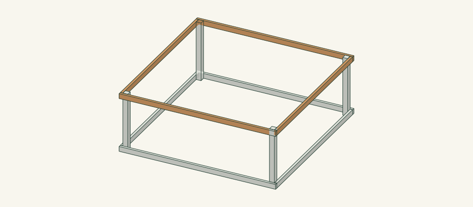
Loading the 3D view…
Drag to turn. Pinch or use + / − to zoom. The written step covers workholding and tool use.
Scroll or swipe the enlarged drawing to read its dimensions. Choose Fit to see the whole drawing again.
Fit the upper frame at 16.5 in above the post bottoms, then repeat the same twelve-screw arrangement.
Check: Total height is 18 inches and upper/lower squares align without twist.
- 07
Cut and fold the mesh
Lay the top mesh over a clean surface and cut its generous blank. Turn each raw margin inward. Repeat for four side panels, allowing overlapping folded margins at corners.
Close-up · Whole model shows the complete part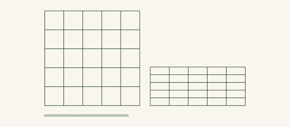
Loading the 3D view…
Drag to turn. Pinch or use + / − to zoom. The written step covers workholding and tool use.
Scroll or swipe the enlarged drawing to read its dimensions. Choose Fit to see the whole drawing again.
Cut one top blank and four side blanks off the frame. The 3D grid represents the blank sizes only, not actual mesh aperture or thickness.
Check: No raw cut mesh will be exposed at a hand-contact edge.
- 08
Capture mesh against solid wood
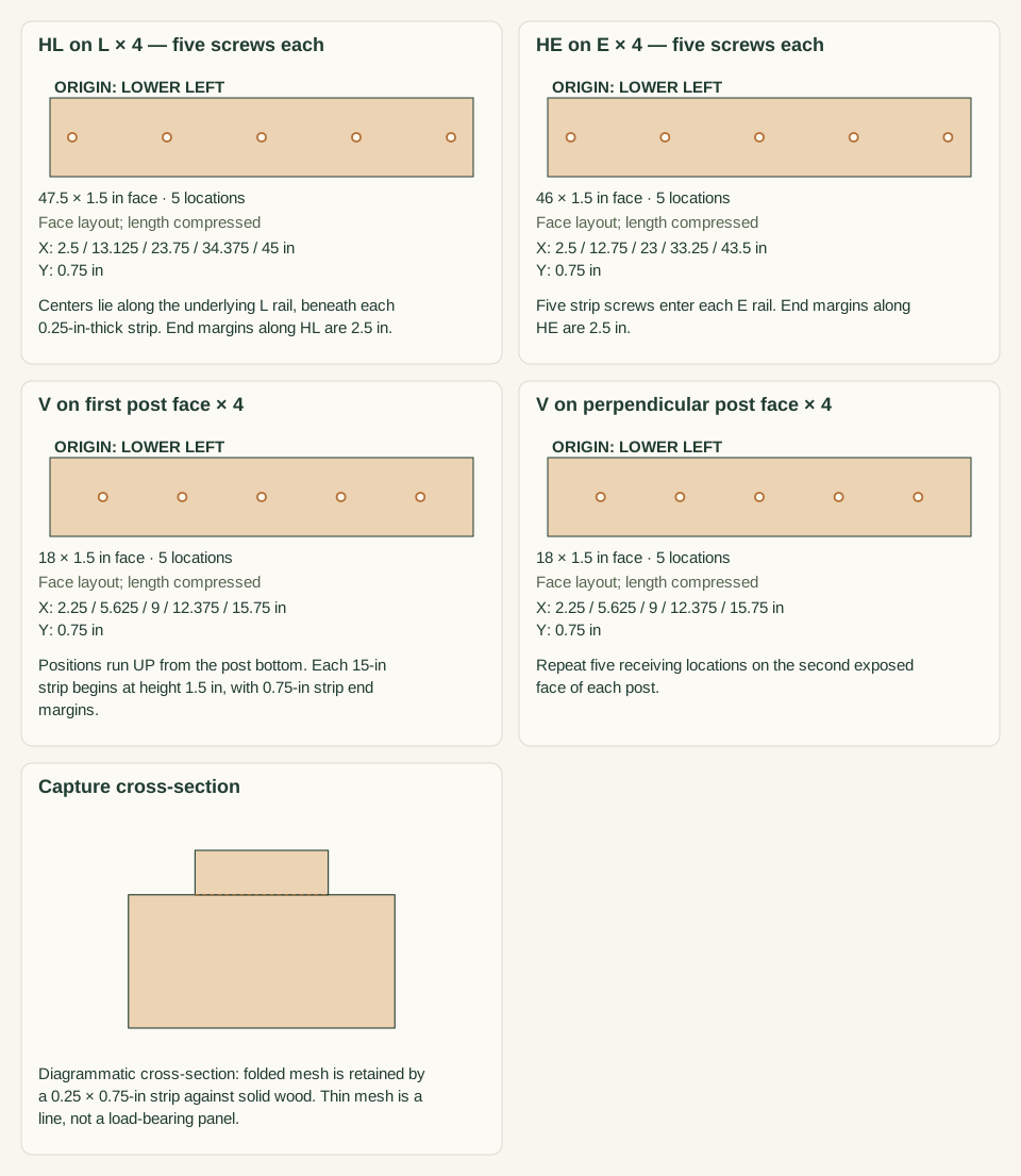
Fit four HL and four HE strips over folded mesh on the outer top and bottom rails. At corners, bring side mesh inward against the post faces. Fit two V strips per post from 1.5 to 16.5 inches above its bottom. Center strips across solid wood. On each horizontal strip mark five holes: 2.5 inches from each end and three equally spaced between, away from the frame screws. On each vertical strip use 0.75-inch end margins and three equal middle positions. Predrill and fit eighty #4 screws.
Close-up · Whole model shows the complete part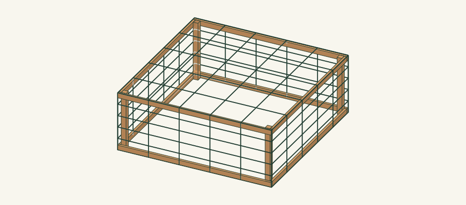
Loading the 3D view…
Drag to turn. Pinch or use + / − to zoom. The written step covers workholding and tool use.
Scroll or swipe the enlarged drawing to read its dimensions. Choose Fit to see the whole drawing again.
Capture the folded mesh with the sixteen retaining strips. The model marks the 80 receiving locations on solid frame wood; strip sections are detailed below. The grid identifies mesh coverage only, not its aperture.
Check: Every retaining screw enters a rail or post; no strip bridges an unsupported mesh edge.
- 09
Use two people to fit the cover
With the bed empty, one person stands on each side. Each grips a lower rail with both hands. Lift together, then center the wooden frame 0.25 inch inside the bed outer edges. Lower it onto the rim without trapping fingers or foliage. Lift off together and store flat out of wind.
Close-up · Whole model shows the complete part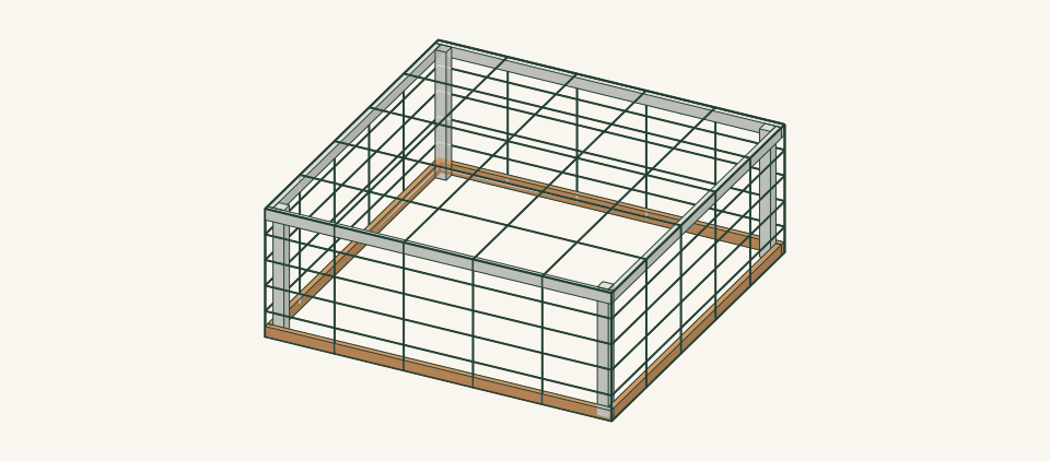
Loading the 3D view…
Drag to turn. Pinch or use + / − to zoom. The written step covers workholding and tool use.
Scroll or swipe the enlarged drawing to read its dimensions. Choose Fit to see the whole drawing again.
Two people lift at opposite lower rails and lower the frame onto the checked bed rim. Keep hands clear of the bearing surface. The grid identifies mesh coverage only, not its aperture.
Check: Two people can lift the cover cleanly; it rests on the rim rather than squeezing the walls.
- 10
Introduce the cover to the crop
Confirm mesh choice, crop growth clearance and pollination needs. Inspect beneath it daily at first. Remove it for tending or weather that can lift it; this design has no site-specific wind anchorage.
Close-up · Whole model shows the complete partLoading the 3D view…
Drag to turn. Pinch or use + / − to zoom. The written step covers workholding and tool use.
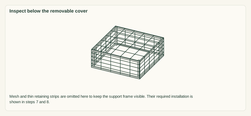
Scroll or swipe the enlarged drawing to read its dimensions. Choose Fit to see the whole drawing again.
Use the cover only while crop clearance, pollination and weather remain suitable. The open structural model does not mean the cover is left unmeshed. The grid identifies mesh coverage only, not its aperture.
Check: Leaves do not press against mesh and air movement remains available.


05 / Keep it sound
Care
After the build
- Use only after confirming the target pest and crop pollination requirements. The mesh does not make the enclosure rodent-proof.
- Inspect after each refit for loose folded margins and corners that have caught on the bed.
Check it each season
- Inspect connections and hand-contact edges before use. Unload before tightening or replacing parts; replace a cracked member rather than adding a screw beside the crack.
- Brush off debris, wipe only as needed and dry with air around the joints. Store dry when the item is not in use.
If something looks wrong
- Cover will not sit flat
- Lift it off with two people. Check the rim is level and free of caps, screw heads and plants. Center the cover ON the rim; it must not slip around the bed walls.
- Frame twists after meshing
- Release the affected strips, square the wood and refit the mesh with less tension.
- A mesh edge opens
- Remove the cover and recapture the folded margin beneath a sound strip.
- Heat or growth crowds plants
- Remove the cover promptly; increase ventilation or stop using this size rather than forcing foliage inside.
Keep exploring