Garden storage · Guide 79
Build a Wall-Mounted Garden Tool Rail
A 32-inch timber rail with replaceable tool brackets located around the tools you own.
01 / See the shape
View the project
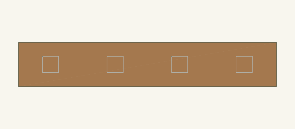
Loading the 3D view…
Drag to turn. Pinch or use + / − to zoom. The written step covers workholding and tool use.
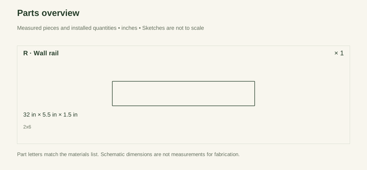
Scroll or swipe the enlarged drawing to read its dimensions. Choose Fit to see the whole drawing again.
Build a Wall-Mounted Garden Tool Rail. Check the dimensions and build steps before cutting.
02 / Plan your build
Before you start
A tool rail works best when its brackets fit guarded tools rather than an imaginary standard shovel. This one spans two identified timber studs. The bracket screws fasten into the rail; four separate mounting screws connect the rail to the wall framing. Keep cutting edges guarded and heavy tools low.
Where it goes
An indoor timber-stud wall with studs 16 inches on center and a verified utility-free mounting zone; not masonry, metal studs or drywall-only fixings.
Footprint: 32-inch-wide rail, 5.5 inches high; the illustrated holders project 4 inches beyond its 1.5-inch thickness. Allow tool-removal space.
What to expect
Measure accurately, make supported square cuts and drill clamped joints. Plan 2–3 hours including wall and tool checks.
A planning estimate for the hands-on work, once the materials are bought and the tools are set up. It has not been timed on a finished build.
Check the spot
- An indoor timber-stud wall with studs 16 inches on center and a verified utility-free mounting zone; not masonry, metal studs or drywall-only fixings.
- Measure the usable stock before marking. Keep the assembly area flat and large enough to clamp the work without reaching across a moving cutter.
Stop and check first if…
- Stop if a part splits, a fixing strips, or the assembled object rocks. Unload it before opening a joint.
- Do not substitute an unknown material section or make the object taller or wider without checking every affected part and joint.
Work safely
- Do not drill where the wall construction or concealed services are uncertain. A stud finder alone does not prove a drill path is clear of pipes or cables. Seek a qualified assessment for an unknown wall.
- Guard every tool blade and point before layout. Keep the rail away from children, seating and walkways. Unload immediately if a bracket turns or the rail pulls away; never use it as a handhold.
Budget
We have not put a price on this one yet. Lumber and hardware prices change by store and season, so price the list under What you need at your local supplier before you buy.
03 / Gather and cut
What you need
R — Wall rail
1 piece
Untreated surfaced 2 × 6, actual 1.5 × 5.5 in. Buy one nominal 2 × 6 × 4-ft board, actual 1.5 × 5.5 in; cut one straight 32-inch rail.
Measure your boards before cutting. Build to the finished sizes written here, not the nominal lumber label.
K — Replaceable tool bracket
4 pieces
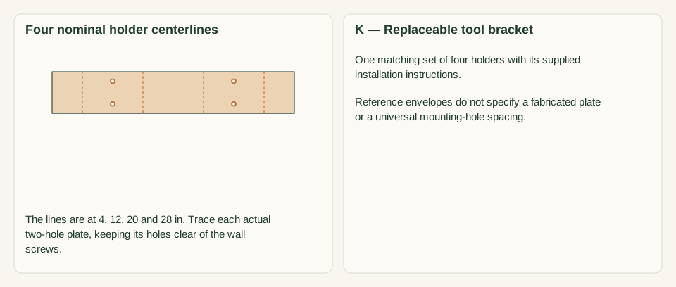
Four paired-prong tool holders approved by their maker for timber mounting, each with exactly two #8-compatible mounting holes and a metal plate 1/16 to 1/8 in thick. One matching set of four holders with its supplied installation instructions.
Use holders that permit two #8 × 1.25-inch wood screws through the plate. Reject products needing a different pattern or screw. A hook rating is not a rating for the whole wall installation.
Wall screws
4 items
#10 × 4-inch wood screws with suitable head or washers for the selected structural timber fixing application Purchase at least 4; keep spare hardware separate from the installed count.
Pilot and installation must match the actual chosen product. Verify penetration and concealed services before drilling.
Bracket screws
8 items
#8 × 1.25-inch screws only if explicitly permitted by the selected bracket instructions Purchase at least 8; keep spare hardware separate from the installed count.
Eight total; two per selected two-hole plate. Plate thickness must be 1/16 to 1/8 in, with this screw accepted by the holder maker.
Tool labels
4 items
Four durable tool-location labels Buy a sheet of labels or use four pieces of suitable labeling tape.
Write the tool names and stick below the holders without covering screw heads.
Cut list
| Piece | How many | Cut length | Note |
|---|---|---|---|
| R — Wall rail | 1 | 32 × 5.5 × 1.5 in | Finished length × width × thickness; square ends unless the detail says otherwise. |
Tools
- Tape or rule, square and sharp pencil
- Clamps, a flat bench and sacrificial backing
- Suitable guarded saw for the specified stock
- Drill/driver, depth stop and bits matched to the chosen screws
- Fine abrasive and a dust brush
- Spirit level; stud finder and appropriate utility-location checks; chosen holder templates; pencil or transfer punch; countersink and depth-stop bits
- Marker or pen for the four tool labels
Protective gear
- Eye protection during cutting and drilling
- Hearing protection and dust collection appropriate to the actual tools
- Closed footwear; keep loose clothing and gloves away from rotating cutters
04 / Put it together
Build steps
- 01
Lay out the guarded tools
Arrange the actual tools on the floor with blade and point guards fitted. Measure the bracket grip and the clearance needed to remove each one without hitting its neighbor. Choose holders that match those dimensions.
Close-up · Whole model shows the complete part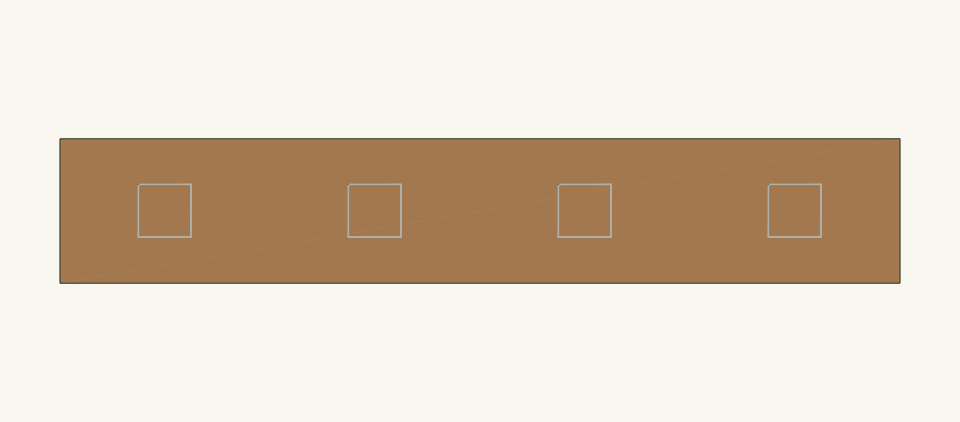
Loading the 3D view…
Drag to turn. Pinch or use + / − to zoom. The written step covers workholding and tool use.
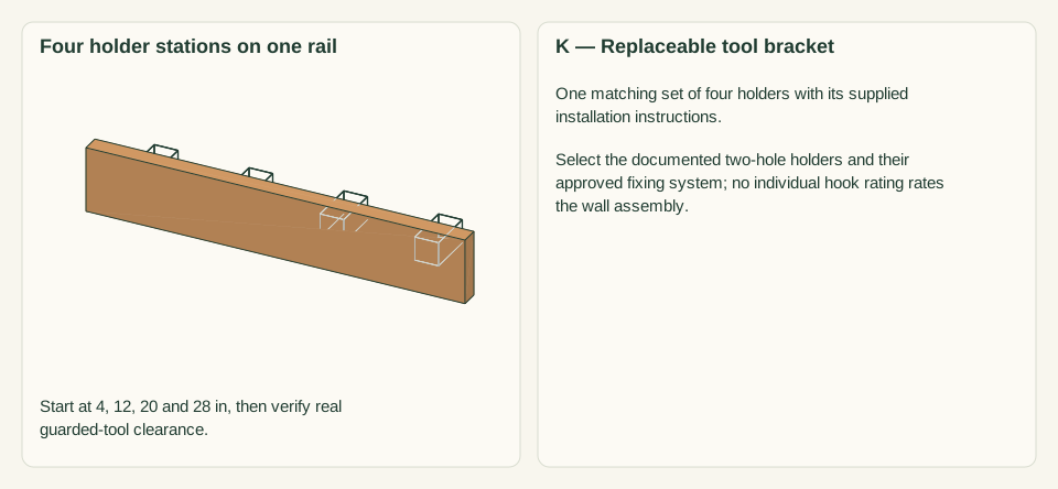
Scroll or swipe the enlarged drawing to read its dimensions. Choose Fit to see the whole drawing again.
Lay out the guarded tools and select holders first. The four outlines show holder space, not supplied hardware or a universal tool shape.
Check: Four chosen tools fit within the 32-inch layout without exposed cutting edges.
- 02
Verify wall framing and services
Identify two timber stud centers 16 inches apart and check the proposed drilling zones for cables, pipes and other services. Stop for an unknown wall, metal framing or inaccessible hidden services.
Close-up · Whole model shows the complete part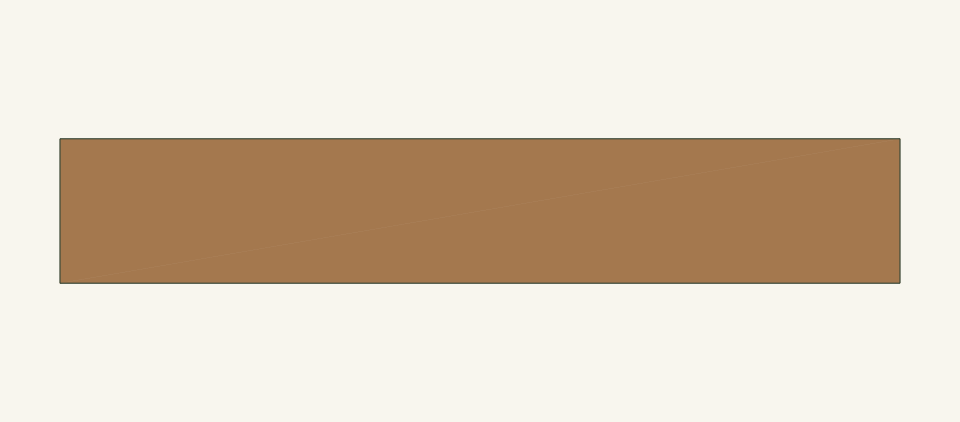
Loading the 3D view…
Drag to turn. Pinch or use + / − to zoom. The written step covers workholding and tool use.
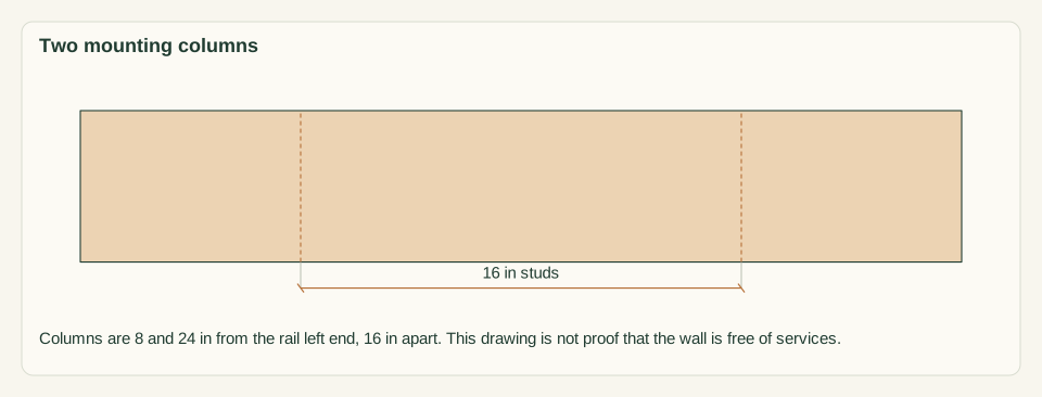
Scroll or swipe the enlarged drawing to read its dimensions. Choose Fit to see the whole drawing again.
Identify the two actual studs and clear drill paths before using the mounting pattern.
Check: Both mounting columns are positively identified on safe timber framing.
- 03
Cut and inspect the rail
Cut a 32-inch piece of actual 1.5 × 5.5 wood. Check for twist and defects at x 8 and 24. Ease exposed corners and inspect the back face so the rail can seat against the wall without debris.
Close-up · Whole model shows the complete part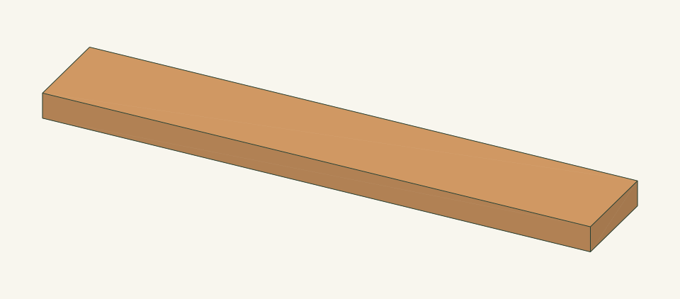
Loading the 3D view…
Drag to turn. Pinch or use + / − to zoom. The written step covers workholding and tool use.
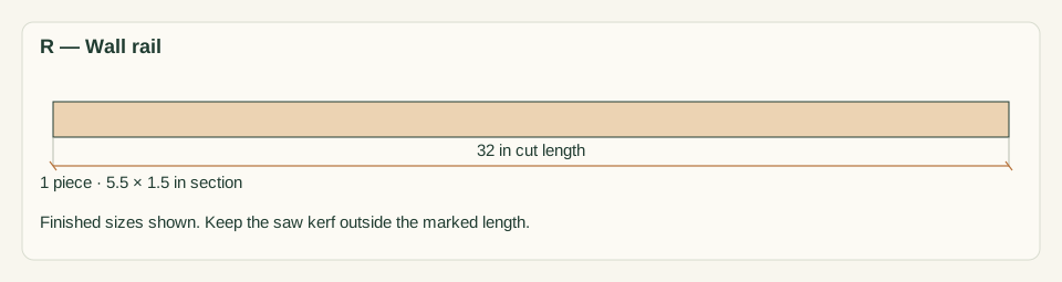
Scroll or swipe the enlarged drawing to read its dimensions. Choose Fit to see the whole drawing again.
Cut one straight rail and inspect its full mounting area. Holders are deliberately absent while preparing the wood.
Check: The rail is straight, sound and the actual thickness is recorded.
- 04
Position the rail and mark mounting height
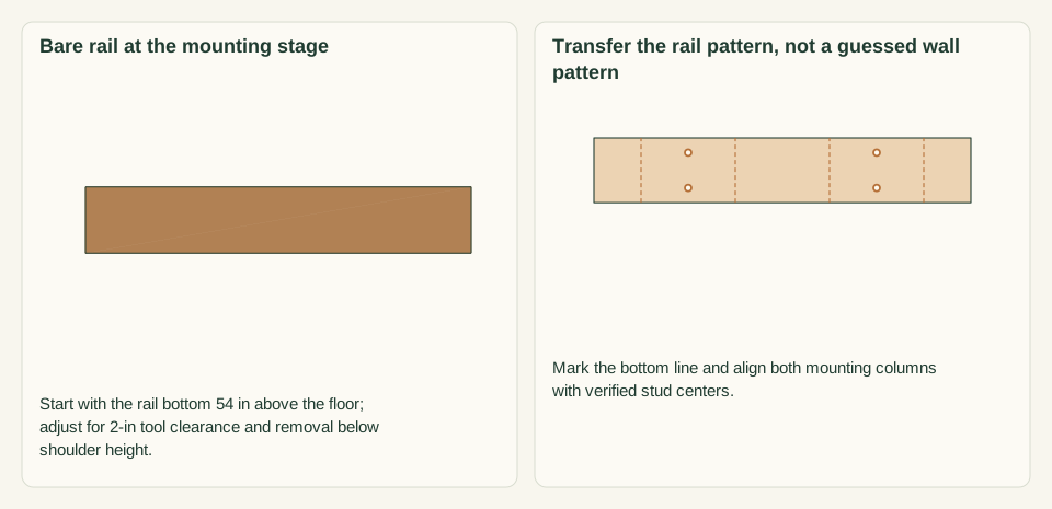
Start with the rail bottom 54 inches above the floor. Hold the bare rail level with x=8 and x=24 inches centered on the verified studs. Check each hanging, guarded tool will clear the floor by at least 2 inches and can be lifted out without reaching above shoulder height. Change the HEIGHT before drilling if needed; stop if no position meets both needs. Mark the chosen bottom line.
Close-up · Whole model shows the complete part
Loading the 3D view…
Drag to turn. Pinch or use + / − to zoom. The written step covers workholding and tool use.
Scroll or swipe the enlarged drawing to read its dimensions. Choose Fit to see the whole drawing again.
Position the bare rail level at the selected height before transferring its holes to the wall.
Check: Mounting height is measured and recorded; both screw columns align with timber studs.
- 05
Transfer the wall holes from the rail
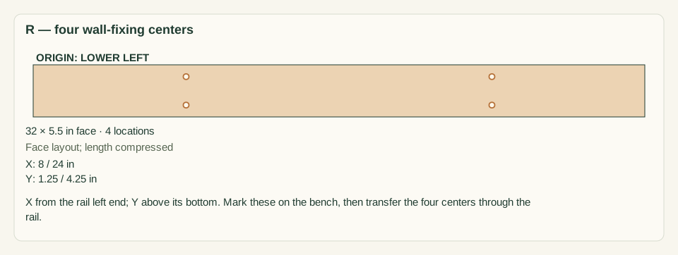
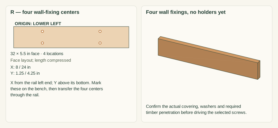
On the bench mark x=8/24 inches and heights 1.25/4.25 from the rail bottom. Clamp and drill rail clearances for the selected wall screws. Hold the drilled rail level at the marked wall line; transfer all four centers through it. Remove the rail. After verifying each path is clear of services, drill product-matched stud pilots at those marks with a depth stop.
Close-up · Whole model shows the complete part
Loading the 3D view…
Drag to turn. Pinch or use + / − to zoom. The written step covers workholding and tool use.
Scroll or swipe the enlarged drawing to read its dimensions. Choose Fit to see the whole drawing again.
Drill rail clearances while it is supported on the bench. Transfer them to the verified wall before drilling the separate stud pilots.
Check: Four transferred wall marks match the rail; pilot depth suits the verified wall and screw.
- 06
Fasten the bare rail level
Hold the rail at its marked height and align the four holes. Fit four #10 × 4-inch wall screws using the chosen product instructions. Confirm their required timber penetration: subtract the 1.5-inch rail, actual wall covering and any washer thickness from 4 inches. Tighten evenly without crushing the covering.
Close-up · Whole model shows the complete part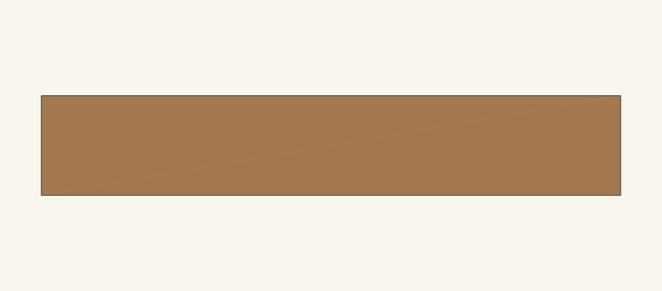
Loading the 3D view…
Drag to turn. Pinch or use + / − to zoom. The written step covers workholding and tool use.
Scroll or swipe the enlarged drawing to read its dimensions. Choose Fit to see the whole drawing again.
Fasten the bare rail to the two verified studs. Bracket holes are a later, separate pattern.
Check: The rail is level, all four screws enter verified studs, and no fixing relies on drywall alone.
- 07
Transfer each holder template
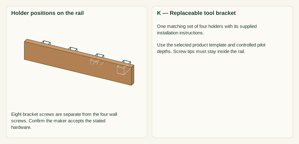
Start bracket centerlines at 4, 12, 20 and 28 inches from the rail left end. Lay out the actual guarded tools first. Place each two-hole holder plate centrally within the 5.5-inch rail height and trace its real holes. Keep all holes clear of the four wall-fixing paths and at least 0.75 inch from a rail edge.
Close-up · Whole model shows the complete part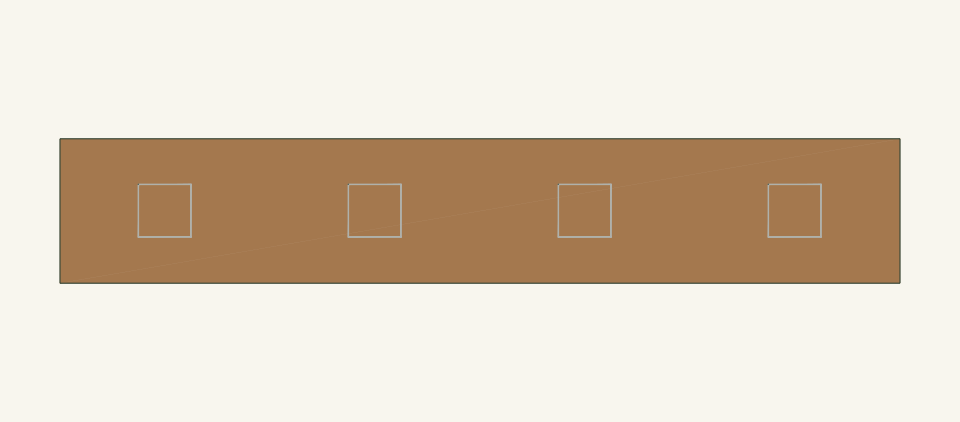
Loading the 3D view…
Drag to turn. Pinch or use + / − to zoom. The written step covers workholding and tool use.
Scroll or swipe the enlarged drawing to read its dimensions. Choose Fit to see the whole drawing again.
Place the actual holder templates and check the tool spacing before adding bracket holes.
Check: Eight bracket holes are marked from the actual product, without crossing wall screws.
- 08
Fit four compatible tool holders
Use only the two-hole holders selected in step 1. Drill depth-controlled product-matched pilots into the rail, then install eight #8 × 1.25-inch screws. With a 1/16 to 1/8-inch plate, nominal wood entry is 1.1875 to 1.125 inches; screw tips remain within the 1.5-inch rail. Stop if the maker requires different fasteners.
Close-up · Whole model shows the complete part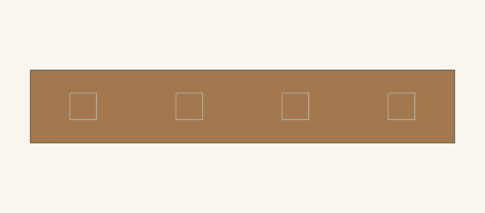
Loading the 3D view…
Drag to turn. Pinch or use + / − to zoom. The written step covers workholding and tool use.
Scroll or swipe the enlarged drawing to read its dimensions. Choose Fit to see the whole drawing again.
Fit four compatible holders using their real two-hole patterns. The model does not invent the unspecified product holes.
Check: Each holder uses its two approved screws and the tips do not enter the wall behind the rail.
- 09
Load one guarded tool at a time
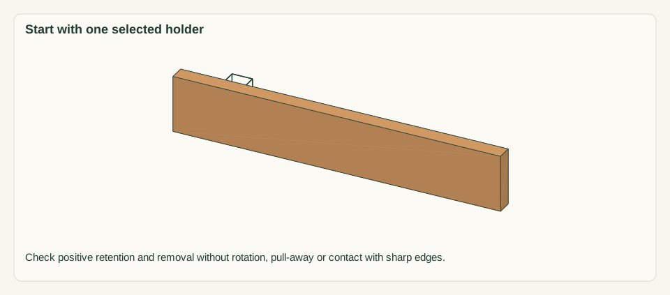
Start with the lightest tool and verify positive seating. Add the others while keeping hands away from sharp edges. Stop if any holder rotates or the rail separates from the wall.
Close-up · Whole model shows the complete part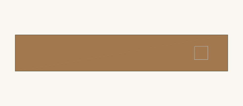
Loading the 3D view…
Drag to turn. Pinch or use + / − to zoom. The written step covers workholding and tool use.
Scroll or swipe the enlarged drawing to read its dimensions. Choose Fit to see the whole drawing again.
Check one guarded tool at a time rather than loading every holder at once. The first outline indicates the first holder position.
Check: Tools are retained individually and can be removed without disturbing neighbors.
- 10
Label places and inspect
Mark the intended tool location below each holder. Keep the floor below clear, inspect screws periodically and remove the tools before moving a bracket. Replace damaged holes or wood rather than adding an adjacent screw casually.
Close-up · Whole model shows the complete partLoading the 3D view…
Drag to turn. Pinch or use + / − to zoom. The written step covers workholding and tool use.
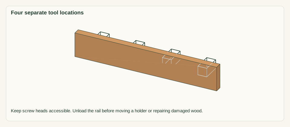
Scroll or swipe the enlarged drawing to read its dimensions. Choose Fit to see the whole drawing again.
Label the four intended tool places and inspect the rail and holders before reuse.
Check: Nothing projects into walking space and every blade or point has a guard.


05 / Keep it sound
Care
After the build
- A hook’s individual rating does not establish the wall assembly’s capacity. Check the actual bracket, screw and wall system together.
- Keep this rail away from children and do not place it over seating, play space or a frequently used passage.
Check it each season
- Inspect connections and hand-contact edges before use. Unload before tightening or replacing parts; replace a cracked member rather than adding a screw beside the crack.
- Keep the rail and wall dry. Remove guarded tools before cleaning or moving a bracket, and inspect the mounting wood rather than tightening into a damaged hole.
If something looks wrong
- Rail pulls from wall
- Unload immediately and inspect framing engagement and selected screws; never substitute drywall anchors.
- Tool rolls off a holder
- Remove it and choose a bracket designed for that guarded tool’s shape.
- Bracket screws loosen
- Unload that bracket, inspect pilot/wood damage and repair with an appropriate reviewed fixing.
- Tools collide during removal
- Re-lay out the empty rail and preserve stud mounts; do not remove blade guards to save space.
Keep exploring