Garden storage · Guide 82
Build a Ventilated Hose Storage Cabinet
An open-back slatted cabinet with a removable front panel for a loose garden-hose coil.
01 / See the shape
View the project
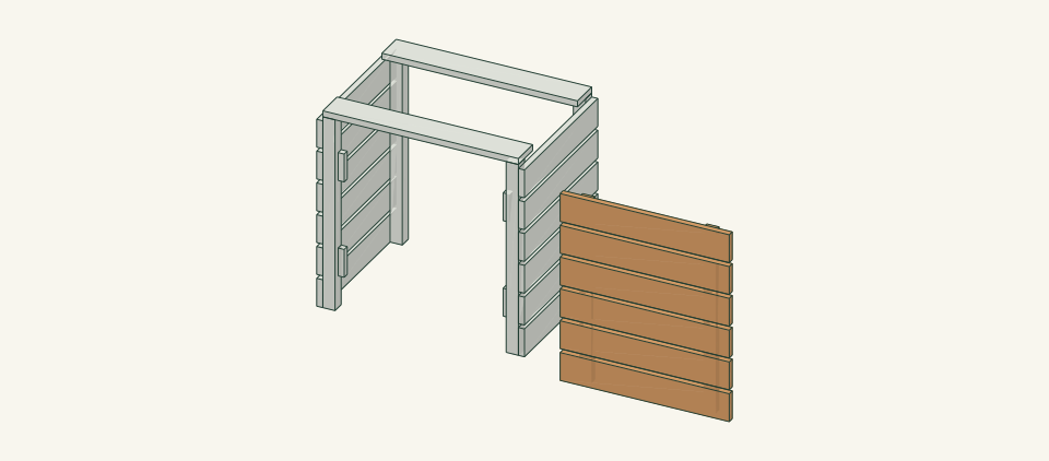
Loading the 3D view…
Drag to turn. Pinch or use + / − to zoom. The written step covers workholding and tool use.
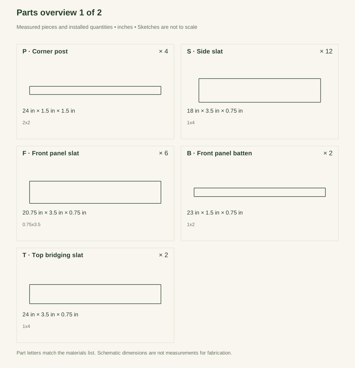
Scroll or swipe the enlarged drawing to read its dimensions. Choose Fit to see the whole drawing again.
Build a Ventilated Hose Storage Cabinet. Check the dimensions and build steps before cutting.
02 / Plan your build
Before you start
This open-back cabinet keeps a drained hose coil tidy without enclosing plumbing or a reel. The slat gaps allow inspection and drying. Turn the front retainers to remove the panel, then remove the hose and tray. Move the wooden frame only when empty; no planter or heavy object belongs on top.
Where it goes
A sheltered level pad beside—not enclosing—a hose connection, with shutoffs and backflow devices fully accessible.
Footprint: 25.5 × 18-inch cabinet; allow space in front to remove the panel and hose, and keep all shutoffs accessible.
What to expect
Measure accurately, make supported square cuts and drill clamped joints. Plan 5–6 hours.
A planning estimate for the hands-on work, once the materials are bought and the tools are set up. It has not been timed on a finished build.
Check the spot
- A sheltered level pad beside—not enclosing—a hose connection, with shutoffs and backflow devices fully accessible.
- Measure the usable stock before marking. Keep the assembly area flat and large enough to clamp the work without reaching across a moving cutter.
Stop and check first if…
- Stop if a part splits, a fixing strips, or the assembled object rocks. Unload it before opening a joint.
- Do not substitute an unknown material section or make the object taller or wider without checking every affected part and joint.
Work safely
- Do not enclose the tap, shutoff or backflow device. Keep hoses out of walking routes and disconnect or drain them as their own instructions require.
- Remove the front panel for hose access, but unload the hose before lifting or moving the cabinet frame. Never sit on its top bridges, add a planter or pull a coupling through a slat gap. Keep turn buttons clear of hands and hose loops.
Budget
We have not put a price on this one yet. Lumber and hardware prices change by store and season, so price the list under What you need at your local supplier before you buy.
03 / Gather and cut
What you need
P — Corner post
4 pieces
Untreated surfaced cedar 2 × 2, actual 1.5 square. Buy one 2 × 2 × 10-ft cedar length, actual 1.5 in square, for four 24-inch posts with kerf and trim.
Measure your boards before cutting. Build to the finished sizes written here, not the nominal lumber label.
S — Side slat
12 pieces
Untreated surfaced cedar 1 × 4, actual 0.75 × 3.5. Three 1 × 4 × 8-ft boards; four 18-inch pieces each.
Measure your boards before cutting. Build to the finished sizes written here, not the nominal lumber label.
F — Front panel slat
6 pieces
Same 0.75 × 3.5 cedar. Buy two 1 × 4 × 8-ft boards for F AND T: each yields three 20.75-in front slats plus one 24-in top bridge.
Measure your boards before cutting. Build to the finished sizes written here, not the nominal lumber label.
B — Front panel batten
2 pieces
Untreated surfaced 1 × 2, actual 0.75 × 1.5. Buy one 1 × 2 × 4-ft board, actual 0.75 × 1.5 in; cut two 23-inch battens.
Measure your boards before cutting. Build to the finished sizes written here, not the nominal lumber label.
T — Top bridging slat
2 pieces
Same 1 × 4 stock. Included in the two boards listed for F; no extra board needed.
Measure your boards before cutting. Build to the finished sizes written here, not the nominal lumber label.
A — Front-panel backing stop
4 pieces
Solid cedar strip, actual 0.75 in square. Buy one 24-inch-long strip; cut four 3.5-inch stops.
Two attach inside each front post and support the panel from behind.
Side/top screws
56 items
#8 × 1.5-in stainless wood screws Purchase at least 56; keep spare hardware separate from the installed count.
Use one consistent product and follow its pilot and driving instructions.
Front-panel screws
24 items
#6 × 1.25-in stainless screws Purchase at least 24; keep spare hardware separate from the installed count.
Use one consistent product and follow its pilot and driving instructions.
Front turn buttons
4 items
Four 3-inch-long exterior flat turn buttons, width at most 0.75 in and plate at most 1/8 in thick, each with one central fixing Buy four matching buttons whose maker permits a #8 × 1-in screw in timber.
Mount to the EXPOSED front post faces at heights 5.75 and 17.75 in; turn horizontally to overlap the panel by 0.625 in.
Hose tray
1 item
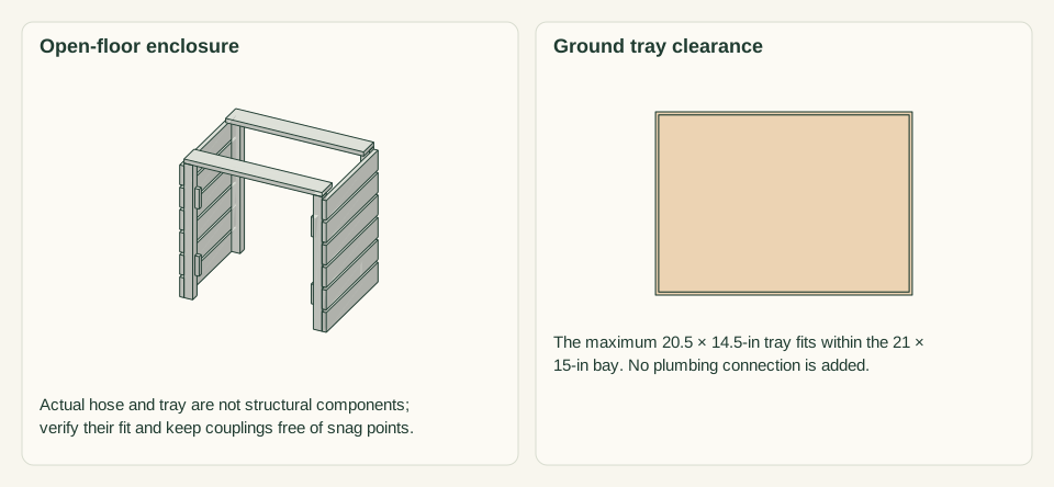
One drainable tray no larger than 20.5 × 14.5 in including its rim Buy one tray that can slide through the open front without lifting the cabinet.
It rests directly on the pad, with the hose on its floor.
Backing-stop screws
8 items
#6 × 1.5-in stainless wood screws Buy a pack with at least eight screws.
Two through each 0.75-in stop into its post: 0.75-in bite.
Turn-button screws
4 items
#8 × 1-in exterior screws accepted by the button maker Buy four matching screws.
At most 1/8-in plate leaves at least 0.875 in in the post; do not use a different product pattern.
Cut list
| Piece | How many | Cut length | Note |
|---|---|---|---|
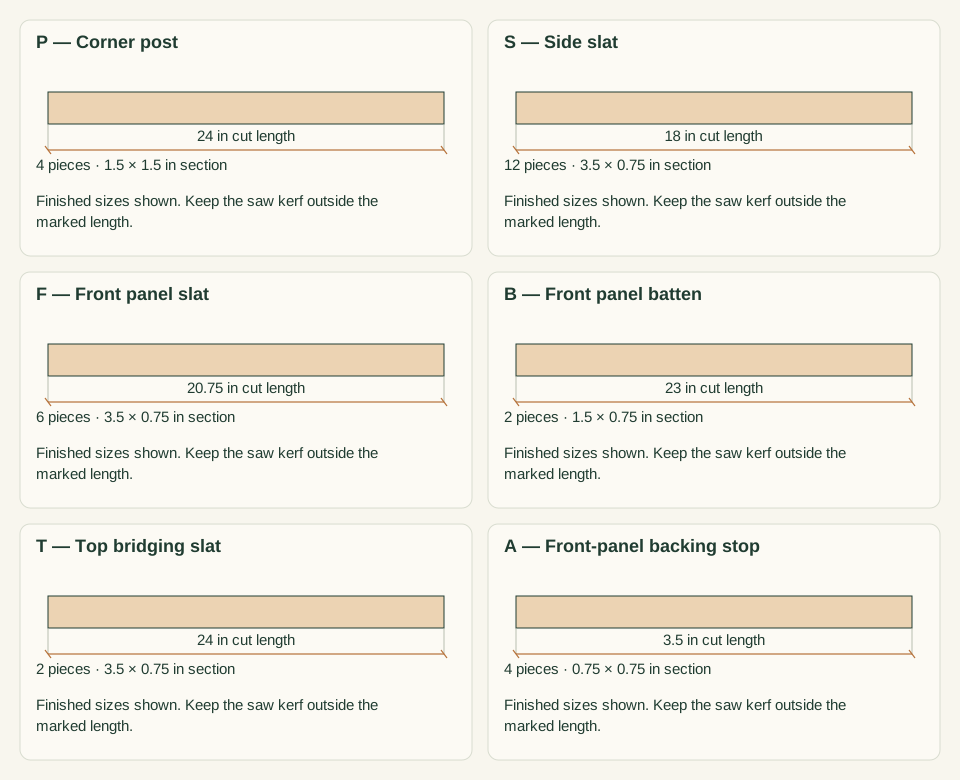
| P — Corner post | 4 | 24 × 1.5 × 1.5 in | Finished length × width × thickness; square ends unless the detail says otherwise. |
| S — Side slat | 12 | 18 × 3.5 × 0.75 in | Finished length × width × thickness; square ends unless the detail says otherwise. |
| F — Front panel slat | 6 | 20.75 × 3.5 × 0.75 in | Finished length × width × thickness; square ends unless the detail says otherwise. |
| B — Front panel batten | 2 | 23 × 1.5 × 0.75 in | Finished length × width × thickness; square ends unless the detail says otherwise. |
| T — Top bridging slat | 2 | 24 × 3.5 × 0.75 in | Finished length × width × thickness; square ends unless the detail says otherwise. |
| A — Front-panel backing stop | 4 | 3.5 × 0.75 × 0.75 in | Finished length × width × thickness; square ends unless the detail says otherwise. |
Tools
- Tape or rule, square and sharp pencil
- Clamps, a flat bench and sacrificial backing
- Suitable guarded saw for the specified stock
- Drill/driver, depth stop and bits matched to the chosen screws
- Fine abrasive and a dust brush
Protective gear
- Eye protection during cutting and drilling
- Hearing protection and dust collection appropriate to the actual tools
- Closed footwear; keep loose clothing and gloves away from rotating cutters
04 / Put it together
Build steps
- 01
Measure the drained hose coil
Coil the actual drained hose loosely without forcing tight bends. Measure its width and depth. Choose a clear spot that leaves the tap, shutoff and backflow device entirely accessible.
Close-up · Whole model shows the complete part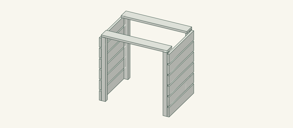
Loading the 3D view…
Drag to turn. Pinch or use + / − to zoom. The written step covers workholding and tool use.
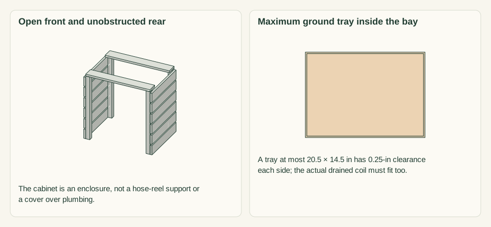
Scroll or swipe the enlarged drawing to read its dimensions. Choose Fit to see the whole drawing again.
Measure the drained hose coil and its removal route before constructing the enclosure.
Check: The coil fits the cabinet’s open floor area without squeezing plumbing.
- 02
Cut and label all wooden parts
Cut four 24-inch posts, twelve 18-inch side slats, six 20.75-inch front slats, two 24-inch top bridges, two 23-inch battens and four 3.5-inch stops. Use each part’s actual section from the cut list, keeping kerf outside the lengths. Label front and rear posts and mark side-slat lower edges at 0, 4, 8, 12, 16 and 20 inches.
Close-up · Whole model shows the complete part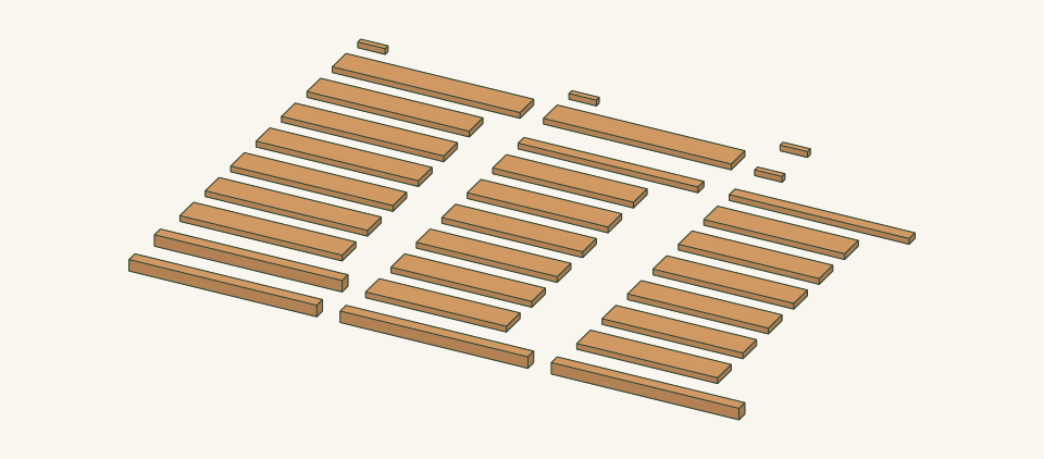
Loading the 3D view…
Drag to turn. Pinch or use + / − to zoom. The written step covers workholding and tool use.
Scroll or swipe the enlarged drawing to read its dimensions. Choose Fit to see the whole drawing again.
Cut and label all wood groups before assembly. Front slats, top bridges, battens and stops have different lengths.
Check: All 30 wooden pieces are cut and labeled; the six row marks match on every post.
- 03
Build two slatted side panels
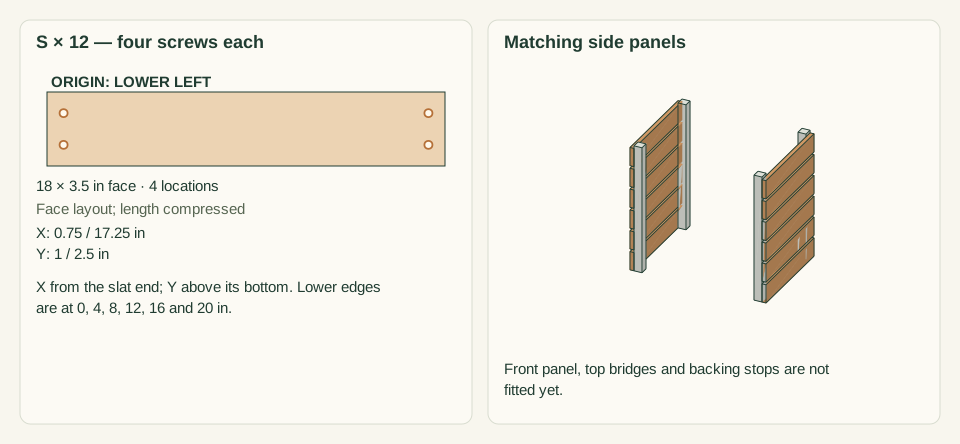
Clamp six 18-inch side slats to each post pair with lower edges at 0, 4, 8, 12, 16 and 20 inches. Screw lines are 0.75 inch from each slat end, with holes 1 and 2.5 inches above its lower edge. Fit 48 #8 × 1.5-inch screws into posts.
Close-up · Whole model shows the complete part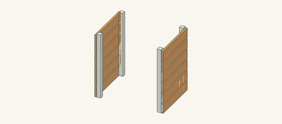
Loading the 3D view…
Drag to turn. Pinch or use + / − to zoom. The written step covers workholding and tool use.
Scroll or swipe the enlarged drawing to read its dimensions. Choose Fit to see the whole drawing again.
Build two matching slatted side panels before joining them. Six rows leave five gaps on each side.
Check: The two side panels match and each has FIVE 0.5-inch gaps.
- 04
Set the sides and fasten the top bridges
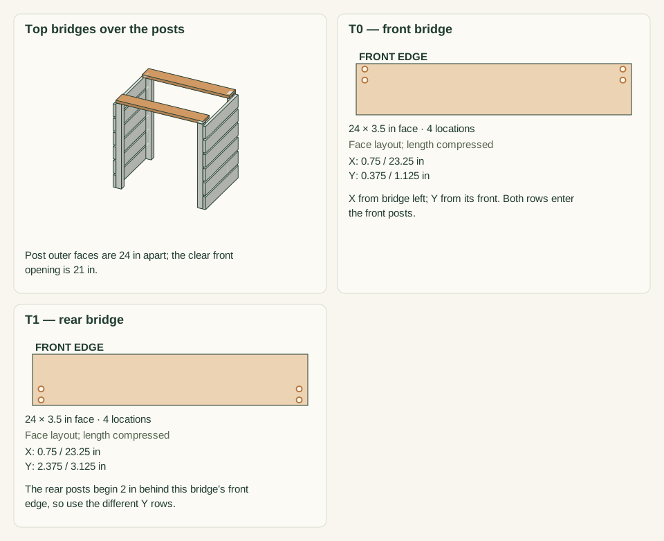
Stand the sides so the outer post faces are 24 inches apart and the clear gap between front posts is 21 inches. Fit two 24-inch top bridges flush with the outer post edges. Mark two holes per post: centered across it, 0.375 and 1.125 inches from its front face. Fit eight #8 × 1.5-inch screws downward into post tops.
Close-up · Whole model shows the complete part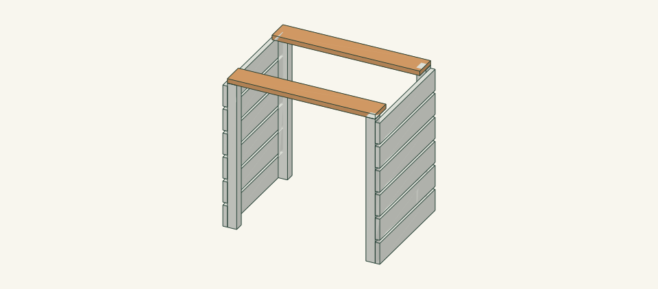
Loading the 3D view…
Drag to turn. Pinch or use + / − to zoom. The written step covers workholding and tool use.
Scroll or swipe the enlarged drawing to read its dimensions. Choose Fit to see the whole drawing again.
Connect the two sides with the front and rear top bridges. Screws enter the four post tops.
Check: Outside cladding is 25.5 × 18 inches; top height is 24.75 inches.
- 05
Size the removable front and battens
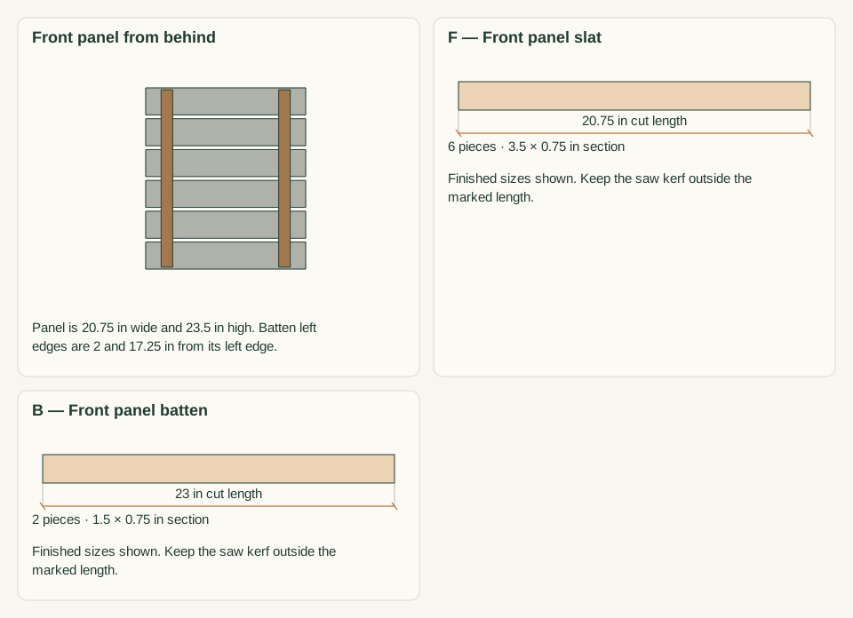
Lay six 20.75-inch F slats at 4-inch pitch, with five 0.5-inch gaps. The panel is 23.5 inches high. Place 23-inch battens behind it, with bottoms 0.25 inch above its bottom. Put their left edges 2 and 17.25 inches from the panel left edge. This keeps them well inside the posts.
Close-up · Whole model shows the complete part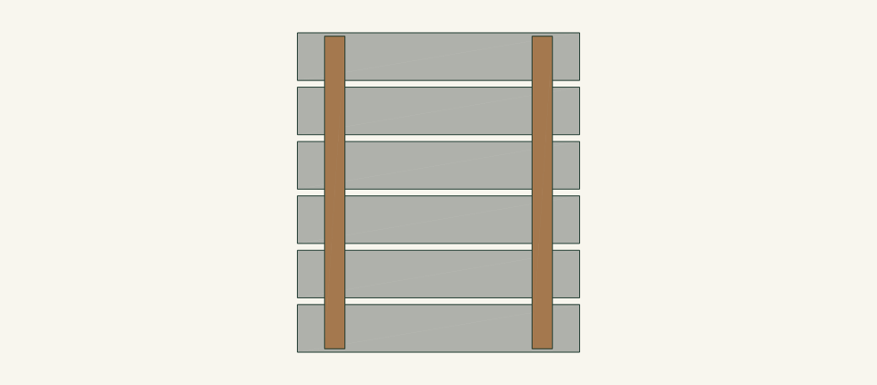
Loading the 3D view…
Drag to turn. Pinch or use + / − to zoom. The written step covers workholding and tool use.
Scroll or swipe the enlarged drawing to read its dimensions. Choose Fit to see the whole drawing again.
Lay out the removable front independently. The battens are behind the six front slats, clear of both posts.
Check: A 20.75-inch panel fits the 21-inch opening with 1/8 inch clear on each side.
- 06
Fasten battens and fit backing stops
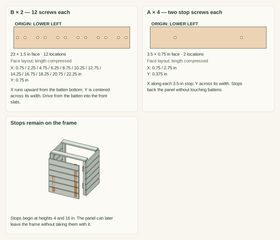
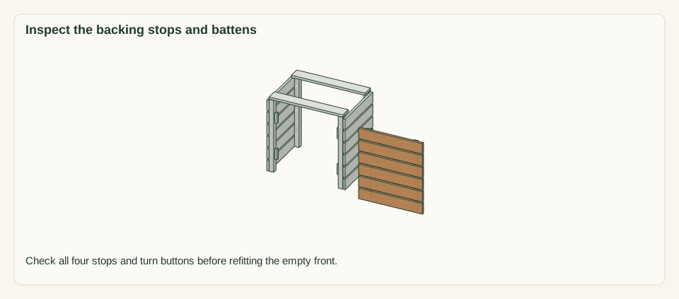
Clamp the battens to the front slats. At each overlap drill two holes centered across the batten, 1 and 2.5 inches above the slat bottom. Drive 24 #6 × 1.25-inch screws FROM THE BATTEN into the slats. Attach two 3.5-inch A stops to each front post inside face, bottoms at 4 and 16 inches; their front faces sit 0.75 inch behind the post fronts. Fix each with two #6 × 1.5-inch screws 0.75 inch from its ends.
Close-up · Whole model shows the complete part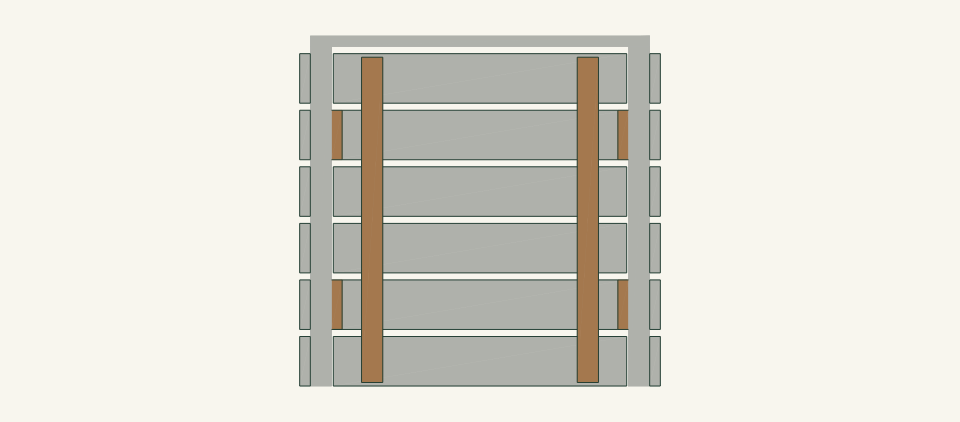
Loading the 3D view…
Drag to turn. Pinch or use + / − to zoom. The written step covers workholding and tool use.
Scroll or swipe the enlarged drawing to read its dimensions. Choose Fit to see the whole drawing again.
Fasten the battens from behind and add the four backing stops to the posts. The front is displaced only to expose these attachments.
Check: Panel battens clear posts; four stops support the panel from behind, without touching the battens.
- 07
Mount the turn buttons on exposed posts
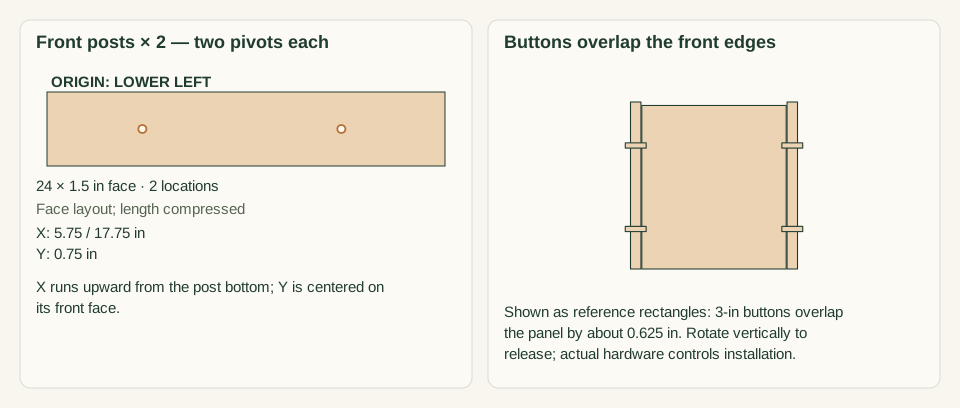
Set the front panel on the pad between the posts, with its back against the four stops. Its front is flush with the post fronts. On each exposed post face, center two turn-button screws at 5.75 and 17.75 inches above the pad. Use the four selected #8 × 1-inch screws. Vertical buttons release the panel; horizontal buttons overlap its edge by about 0.625 inch.
Close-up · Whole model shows the complete part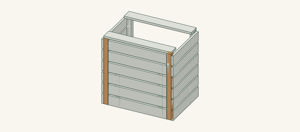
Loading the 3D view…
Drag to turn. Pinch or use + / − to zoom. The written step covers workholding and tool use.
Scroll or swipe the enlarged drawing to read its dimensions. Choose Fit to see the whole drawing again.
Attach turn-button pivots to the exposed front posts, not to the removable slats. The four symbols identify pivot centers only.
Check: Buttons hold the panel outward and stops hold it inward; the empty panel slides out without binding.
- 08
Check access and ventilation
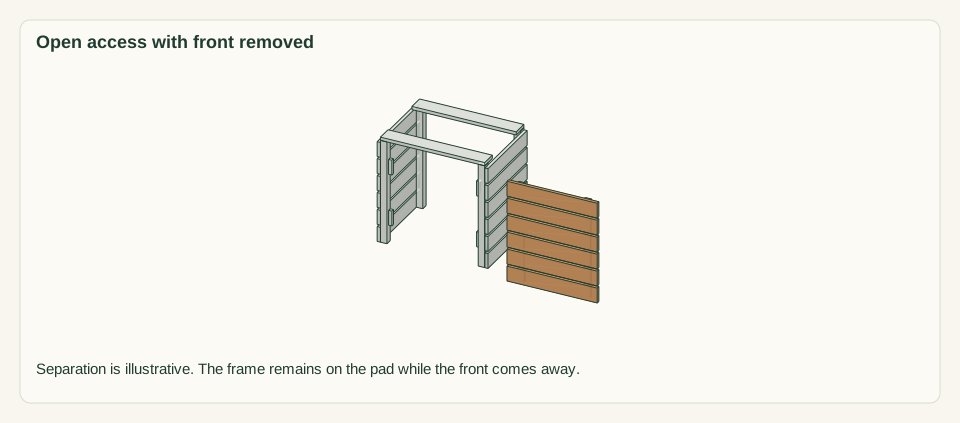
Set the cabinet on its intended level pad. Open the front and verify that the rear remains unobstructed. Check that nothing covers a required shutoff, vent or backflow device.
Close-up · Whole model shows the complete part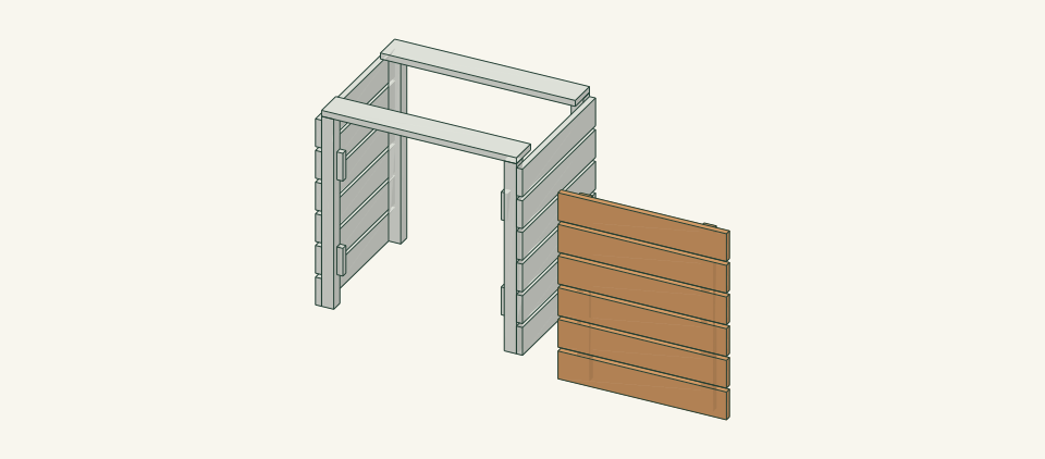
Loading the 3D view…
Drag to turn. Pinch or use + / − to zoom. The written step covers workholding and tool use.
Scroll or swipe the enlarged drawing to read its dimensions. Choose Fit to see the whole drawing again.
Release and set aside the front to check access. Do not enclose the tap, shutoff or backflow device.
Check: The hose connection can be inspected without lifting or dismantling the cabinet.
- 09
Place the hose on a drainable tray
Put the selected tray on the ground inside the cabinet and add the drained hose coil. Keep couplings away from slat joints and use no sharp cutout as a hose guide.
Close-up · Whole model shows the complete part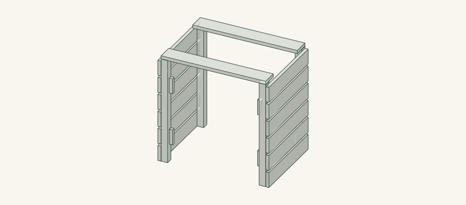
Loading the 3D view…
Drag to turn. Pinch or use + / − to zoom. The written step covers workholding and tool use.
Scroll or swipe the enlarged drawing to read its dimensions. Choose Fit to see the whole drawing again.
The hose and tray sit on the pad, not on the cabinet frame. Keep the front open for loading and removal.
Check: The hose bears on the pad/tray and does not pull on the cabinet when removed.
- 10
Open the front and empty before moving
Drain and disconnect the hose at the accessible connection. Turn the four front retainers vertical and remove the panel while the cabinet stays on its pad. Lift out the drained hose and tray, then move the EMPTY frame for cleaning. Dry the pad and wood, refit the tray and hose, and close the panel after checking all retainers.
Close-up · Whole model shows the complete partLoading the 3D view…
Drag to turn. Pinch or use + / − to zoom. The written step covers workholding and tool use.
Scroll or swipe the enlarged drawing to read its dimensions. Choose Fit to see the whole drawing again.
Open the front before hose access; unload the hose before moving the frame. Clean the separated panel, pad and tray.
Check: The front panel gives access before unloading; the cabinet itself is moved only when empty.


05 / Keep it sound
Care
After the build
- Do not add a planter, seat or heavy lid. This enclosure does not support a hose reel or fixed plumbing.
- Uncoil the hose through the open front; do not pull a coupling through a narrow slat gap.
Check it each season
- Inspect connections and hand-contact edges before use. Unload before tightening or replacing parts; replace a cracked member rather than adding a screw beside the crack.
- Brush off debris, wipe only as needed and dry with air around the joints. Store dry when the item is not in use.
If something looks wrong
- Coil will not fit
- Use a different enclosure rather than forcing a hose into smaller bend radii.
- Front panel jams
- Empty the cabinet and check swollen battens, slat pitch and frame squareness.
- A coupling catches
- Remove the hose through the open front and eliminate sharp hardware; do not enlarge gaps randomly.
- Base stays wet
- Improve the permitted tray/pad drainage and remove the enclosure to inspect; do not redirect runoff toward a building.
Keep exploring