Garden workstations · Guide 74
Build a Three-Tray Bulb-Drying Rack
Three removable slatted trays in a braced open-front rack for clean, ventilated handling.
01 / See the shape
View the project
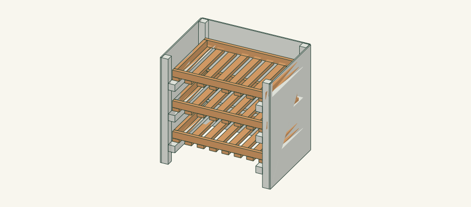
Loading the 3D view…
Drag to turn. Pinch or use + / − to zoom. The written step covers workholding and tool use.
Scroll or swipe the enlarged drawing to read its dimensions. Choose Fit to see the whole drawing again.
Build a Three-Tray Bulb-Drying Rack. Check the dimensions and build steps before cutting.
02 / Plan your build
Before you start
Lift-out trays let you inspect drying bulbs without dumping a whole pile. This compact rack supports each tray on two side runners and leaves space above it for air. Use it for small single-layer batches of bulbs under crop-specific drying guidance, not as a heated food dehydrator.
Where it goes
A sheltered, dry, ventilated work area with a flat bench that supports the entire rack; not direct rain or an overhead storage location.
Footprint: 24.5 × 18.25 in frame size; allow room around it to work and for anything that projects.
What to expect
Measure accurately, make supported square cuts and drill clamped joints. Plan 5–7 hours for the rack and three trays.
A planning estimate for the hands-on work, once the materials are bought and the tools are set up. It has not been timed on a finished build.
Check the spot
- A sheltered, dry, ventilated work area with a flat bench that supports the entire rack; not direct rain or an overhead storage location.
- Measure the usable stock before marking. Keep the assembly area flat and large enough to clamp the work without reaching across a moving cutter.
Stop and check first if…
- Stop if a part splits, a fixing strips, or the assembled object rocks. Unload it before opening a joint.
- Do not substitute an unknown material section or make the object taller or wider without checking every affected part and joint.
Work safely
- Use gloves when handling bulbs and discard damaged material under the crop guidance; wash hands afterward. Keep ornamental bulbs away from food, children and pets.
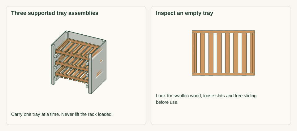
- Carry one empty or lightly filled tray at a time, with both hands. Never lift the loaded rack. Keep wood dust out of the drying area and stop using a swollen, split or sticking tray.
Budget
We have not put a price on this one yet. Lumber and hardware prices change by store and season, so price the list under What you need at your local supplier before you buy.
03 / Gather and cut
What you need
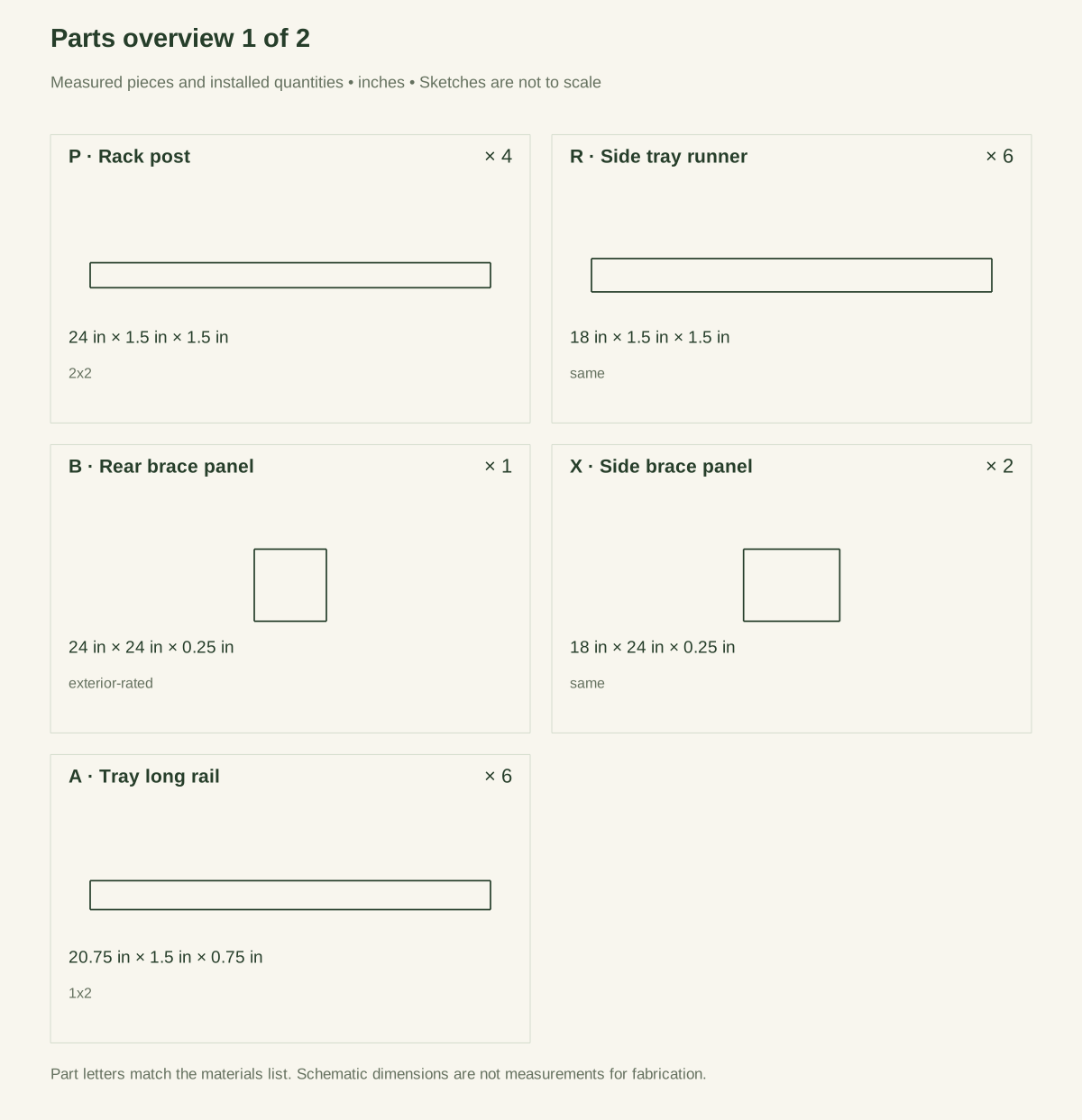
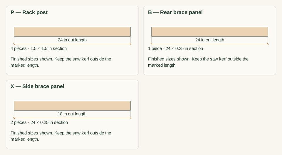
P — Rack post
4 pieces
Untreated surfaced 2 × 2, actual 1.5 square. Buy two nominal 2 × 2 × 8-ft boards, actual 1.5 in square; cut two 24-inch posts from each.
Measure your boards before cutting. Build to the finished sizes written here, not the nominal lumber label.
R — Side tray runner
6 pieces
Same actual 1.5-square stock. Two 2 × 2 × 8-ft boards; three 18-inch runners per board.
Measure your boards before cutting. Build to the finished sizes written here, not the nominal lumber label.
B — Rear brace panel
1 piece
Exterior-rated plywood, actual 0.25 in. Buy one 48 × 96 × 0.25-in exterior plywood sheet for B and both X panels, allowing for kerf and trim.
Measure your boards before cutting. Build to the finished sizes written here, not the nominal lumber label.
X — Side brace panel
2 pieces
Same 0.25-in exterior panel. Cut both 18 × 24-in panels from the sheet listed for B; no extra sheet needed.
Measure your boards before cutting. Build to the finished sizes written here, not the nominal lumber label.
A — Tray long rail
6 pieces
Untreated surfaced 1 × 2, actual 0.75 × 1.5. Two 1 × 2 × 8-ft boards for A; three cuts per board.
Measure your boards before cutting. Build to the finished sizes written here, not the nominal lumber label.
E — Tray end rail
6 pieces
Same 0.75 × 1.5 stock. One 1 × 2 × 8-ft board for E plus kerf.
Measure your boards before cutting. Build to the finished sizes written here, not the nominal lumber label.
S — Tray floor slat
24 pieces
Same 0.75 × 1.5 stock. Four 1 × 2 × 8-ft boards; six 14.75-inch cuts per board.
Measure your boards before cutting. Build to the finished sizes written here, not the nominal lumber label.
Runner screws
24 items
#8 × 2.5-in exterior wood screws Purchase at least 24; keep spare hardware separate from the installed count.
Use one consistent product and follow its pilot and driving instructions.
Tray corner screws
24 items
#6 × 1.5-in stainless wood screws Purchase at least 24; keep spare hardware separate from the installed count.
Use one consistent product and follow its pilot and driving instructions.
Slat screws
48 items
#6 × 1.5-in stainless wood screws Purchase at least 48; keep spare hardware separate from the installed count.
One through each slat end leaves 0.75 in in the 1.5-in-high tray rail.
Brace-panel screws
36 items
#6 × 1-in exterior screws Purchase at least 36; keep spare hardware separate from the installed count.
Use one consistent product and follow its pilot and driving instructions.
Batch labels
3 items
Three durable labels for the separate bulb batches Buy one label sheet or suitable labeling tape and a marker.
Keep each crop label with its tray; do not mix ornamental and edible bulbs.
Cut list
| Piece | How many | Cut length | Note |
|---|---|---|---|
| P — Rack post | 4 | 24 × 1.5 × 1.5 in | Finished length × width × thickness; square ends unless the detail says otherwise. |
| R — Side tray runner | 6 | 18 × 1.5 × 1.5 in | Finished length × width × thickness; square ends unless the detail says otherwise. |
| B — Rear brace panel | 1 | 24 × 24 × 0.25 in | Finished length × width × thickness; square ends unless the detail says otherwise. |
| X — Side brace panel | 2 | 18 × 24 × 0.25 in | Finished length × width × thickness; square ends unless the detail says otherwise. |
| A — Tray long rail | 6 | 20.75 × 1.5 × 0.75 in | Finished length × width × thickness; square ends unless the detail says otherwise. |
| E — Tray end rail | 6 | 13.25 × 1.5 × 0.75 in | Finished length × width × thickness; square ends unless the detail says otherwise. |
| S — Tray floor slat | 24 | 14.75 × 1.5 × 0.75 in | Finished length × width × thickness; square ends unless the detail says otherwise. |
Tools
- Tape or rule, square and sharp pencil
- Clamps, a flat bench and sacrificial backing
- Suitable guarded saw for the specified stock
- Drill/driver, depth stop and bits matched to the chosen screws
- Fine abrasive and a dust brush
- Seven 1.25-inch spacing blocks; countersink bit; shop vacuum
- Marker for the three batch labels
Protective gear
- Eye protection during cutting and drilling
- Hearing protection and dust collection appropriate to the actual tools
- Closed footwear; keep loose clothing and gloves away from rotating cutters
- Gloves for handling bulbs and dirty trays only; remove them before using drills or saws
04 / Put it together
Build steps
- 01
Choose the drying task
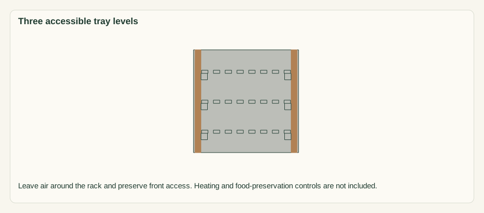
Confirm that the crop guidance calls for ventilated, sheltered drying. Pick a level bench with air around the rack. Do not use this as a heated dehydrator or assume the rack establishes a safe food-preservation process.
Close-up · Whole model shows the complete part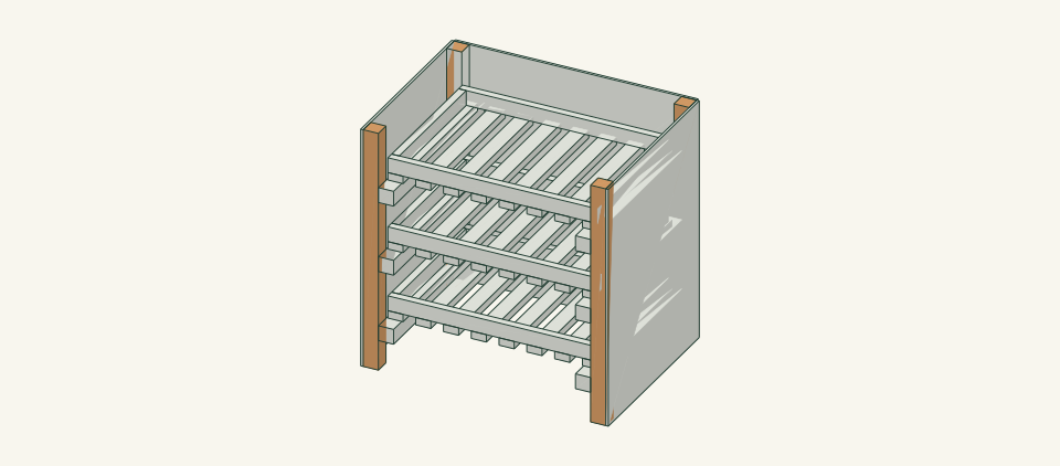
Loading the 3D view…
Drag to turn. Pinch or use + / − to zoom. The written step covers workholding and tool use.
Scroll or swipe the enlarged drawing to read its dimensions. Choose Fit to see the whole drawing again.
Match the crop’s drying process to the finished rack before cutting. The object is a size and access reference, not a drying-performance guarantee.
Check: The selected crop, location and single-layer batch fit the intended use.
- 02
Cut the posts and brace panels
Cut four matching 24-inch posts. Cut one 24 × 24 rear panel and two 18 × 24 side panels. Check that the panels are square and their edges are sound; retain the actual thickness in your layout.
Close-up · Whole model shows the complete part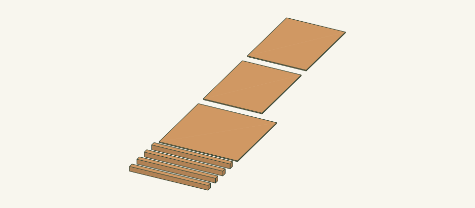
Loading the 3D view…
Drag to turn. Pinch or use + / − to zoom. The written step covers workholding and tool use.
Scroll or swipe the enlarged drawing to read its dimensions. Choose Fit to see the whole drawing again.
Cut the four posts and three brace panels first; trays and runners are separate later operations.
Check: All four posts match and the three panels are flat.
- 03
Mark paired runner levels
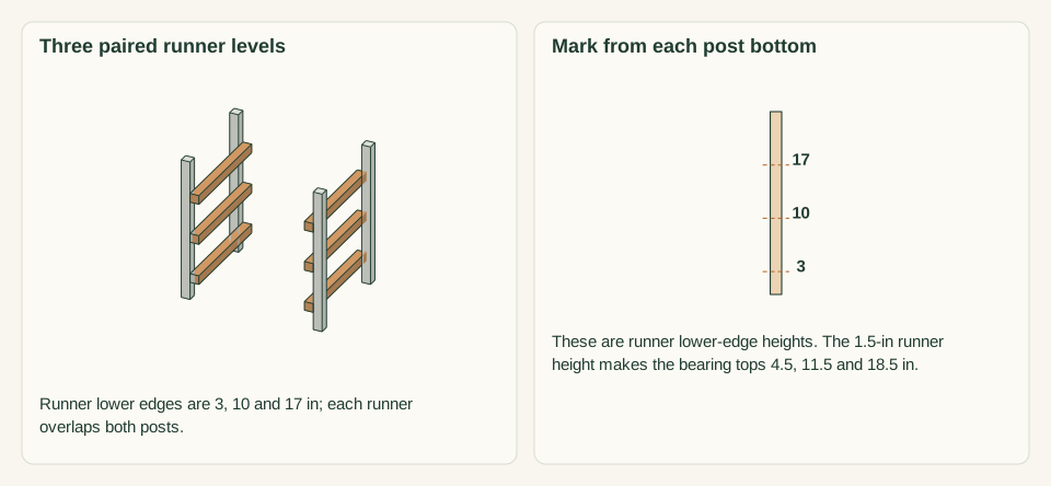
Cut six matching 18-inch runners from actual 1.5-inch-square stock. On the INSIDE faces of each post pair mark runner lower edges at 3, 10 and 17 inches from the post bottoms. The front post outer face is the front of every 18-inch runner; the rear post outer face is flush with its far end. Clamp runners so their 1.5-inch width projects into the bay.
Close-up · Whole model shows the complete part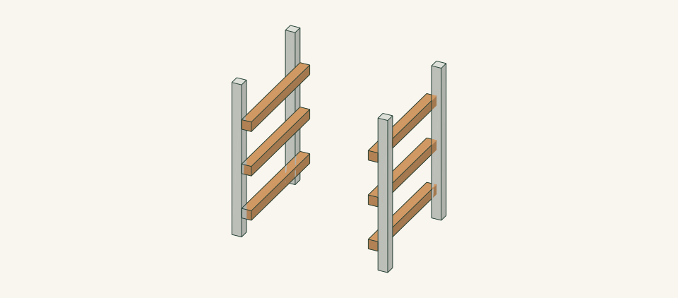
Loading the 3D view…
Drag to turn. Pinch or use + / − to zoom. The written step covers workholding and tool use.
Scroll or swipe the enlarged drawing to read its dimensions. Choose Fit to see the whole drawing again.
Clamp the side runners with their lower edges at the three marked heights and their ends flush to the outer post faces.
Check: Both sides have runner tops at 4.5, 11.5 and 18.5 inches.
- 04
Fasten runners and three brace panels
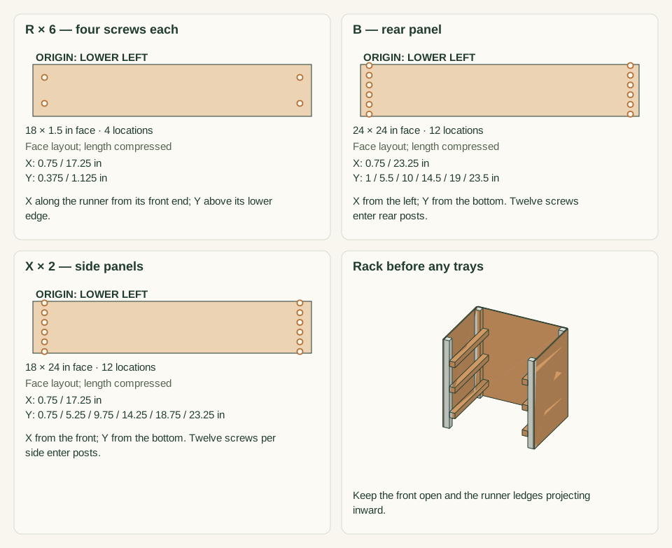
At each runner end mark two #8 × 2.5-inch screws: 0.75 inch from the end and 0.375/1.125 inch above its lower edge. Fasten through runners into posts. Fit side panels outside the posts: hole columns 0.75 and 17.25 inches from the front edge, at heights 0.75, 5.25, 9.75, 14.25, 18.75 and 23.25. Fit rear panel with columns 0.75/23.25 from its left edge and heights 1, 5.5, 10, 14.5, 19 and 23.5. Use 36 #6 × 1-inch panel screws INTO POSTS ONLY.
Close-up · Whole model shows the complete part
Loading the 3D view…
Drag to turn. Pinch or use + / − to zoom. The written step covers workholding and tool use.
Scroll or swipe the enlarged drawing to read its dimensions. Choose Fit to see the whole drawing again.
Complete the rack frame with 24 runner screws and 36 panel screws. The receiving wood for every panel screw is a post.
Check: 24 runner screws and 36 panel screws enter wood; no side-panel screw targets an inset runner.
- 05
Cut three identical tray rings
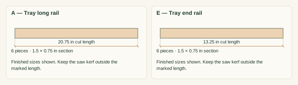
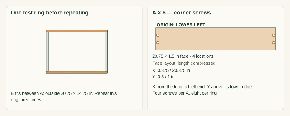
Cut six 20.75-inch long rails and six 13.25-inch ends. Fit the ends between the long rails to give a 20.75 × 14.75 ring. Label one test tray before repeating the other two.
Close-up · Whole model shows the complete part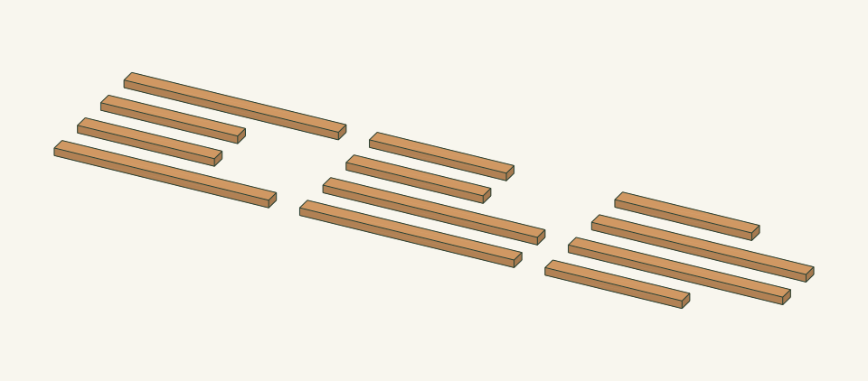
Loading the 3D view…
Drag to turn. Pinch or use + / − to zoom. The written step covers workholding and tool use.
Scroll or swipe the enlarged drawing to read its dimensions. Choose Fit to see the whole drawing again.
Cut twelve tray-ring components. The shorter E members fit between A; they are not interchangeable.
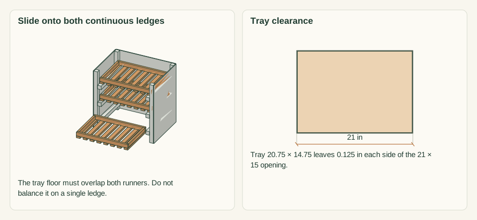
Check: The test ring fits the 21 × 15 opening with 1/8-inch side clearance.
- 06
Fasten three tray rings
Fit E between A and clamp each ring flat. Mark two holes through A at each end: 0.375 inch from the end, at 0.5 and 1 inch above its lower edge. Drill clearance through A and pilots into E; fit eight #6 × 1.5-inch screws per ring. Keep these side paths separate from the vertical floor screws.
Close-up · Whole model shows the complete part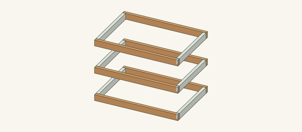
Loading the 3D view…
Drag to turn. Pinch or use + / − to zoom. The written step covers workholding and tool use.
Scroll or swipe the enlarged drawing to read its dimensions. Choose Fit to see the whole drawing again.
Build three identical tray rings without floor slats. Keep their corner screw paths separate from the later underside screws.
Check: Three 20.75 × 14.75-inch rings match; 24 corner screws are installed without splits.
- 07
Cut and space the floor slats
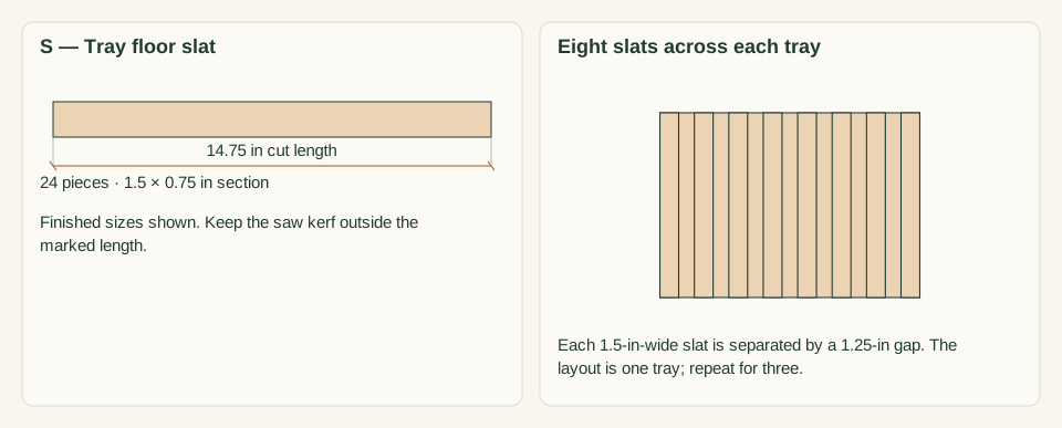
Cut twenty-four 14.75-inch slats from the actual 0.75 × 1.5 stock. Position eight beneath each ring. Use seven 1.25-inch spacers to distribute them along the 20.75-inch tray width.
Close-up · Whole model shows the complete part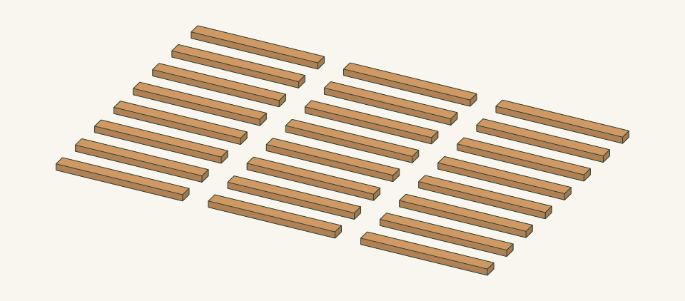
Loading the 3D view…
Drag to turn. Pinch or use + / − to zoom. The written step covers workholding and tool use.
Scroll or swipe the enlarged drawing to read its dimensions. Choose Fit to see the whole drawing again.
Cut 24 identical floor slats, then lay out eight per tray with seven equal gaps.
Check: Slat ends align with the tray depth and all seven gaps are equal.
- 08
Screw slats to the tray rails
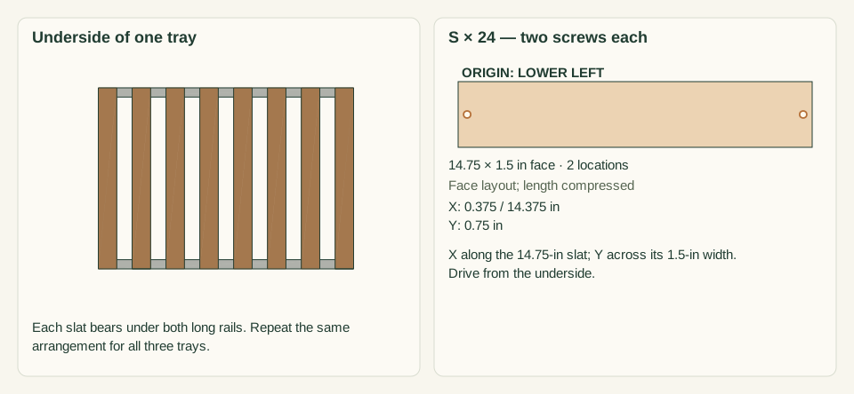
Clamp eight slats under each ring at the measured spacing. Mark one screw at each slat end: centered across its 1.5-inch width and 0.375 inch from the end. Drill clearance through the slat only and a pilot into the long rail. Fit sixteen #6 × 1.5-inch screws per tray, from below. Each passes 0.75 inch of slat and enters the rail another 0.75 inch.
Close-up · Whole model shows the complete part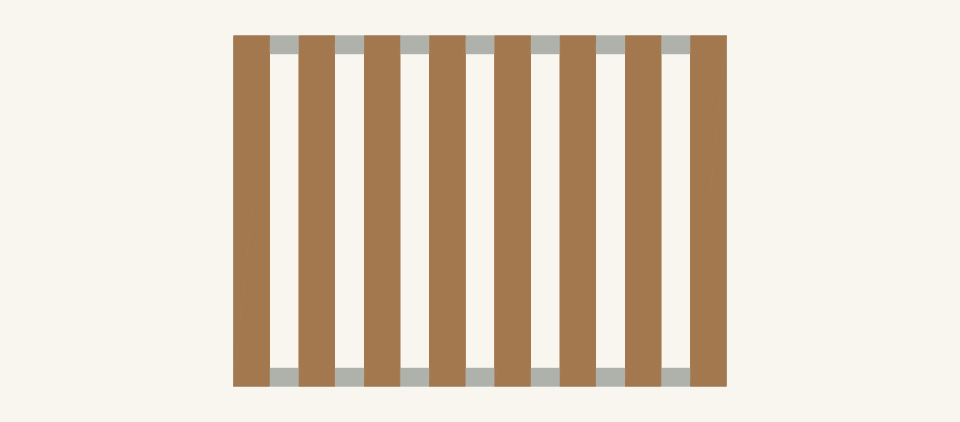
Loading the 3D view…
Drag to turn. Pinch or use + / − to zoom. The written step covers workholding and tool use.
Scroll or swipe the enlarged drawing to read its dimensions. Choose Fit to see the whole drawing again.
Fit the slats beneath the tray rings and drive the floor screws upward into A, not through the ring corner paths.
Check: 48 slat screws are fitted across three trays; no point or head can snag a hand.
- 09
Fit all three trays empty
Slide the trays onto the runners one at a time. Verify continuous bearing along both side edges, smooth withdrawal and clearance beneath the next tray. Do not use a tray that can fall between its runners.
Close-up · Whole model shows the complete part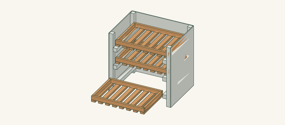
Loading the 3D view…
Drag to turn. Pinch or use + / − to zoom. The written step covers workholding and tool use.
Scroll or swipe the enlarged drawing to read its dimensions. Choose Fit to see the whole drawing again.
Insert the finished empty trays one by one. The lowest tray is separated to show the horizontal withdrawal path.
Check: All trays rest on both runners and can be removed without tilting the rack.
- 10
Load one shallow layer and inspect
Arrange the permitted bulbs so air reaches between them. Do not stack deep piles or block the rack’s open front. Inspect regularly under the chosen crop guidance and remove decayed material promptly.
Close-up · Whole model shows the complete partLoading the 3D view…
Drag to turn. Pinch or use + / − to zoom. The written step covers workholding and tool use.
Scroll or swipe the enlarged drawing to read its dimensions. Choose Fit to see the whole drawing again.
Use shallow separated layers and retain access to every removable tray. The contents are not simulated as proof of drying performance.
Check: Trays are not overloaded and the selected drying conditions remain available.


05 / Keep it sound
Care
After the build
- Keep batches labeled and separate. Move the trays individually rather than lifting a filled rack.
- Use a clean liner suited to the crop only when it does not block necessary air movement; do not claim the wooden surfaces are sanitized.
Check it each season
- Inspect connections and hand-contact edges before use. Unload before tightening or replacing parts; replace a cracked member rather than adding a screw beside the crack.
- Brush off debris, wipe only as needed and dry with air around the joints. Store dry when the item is not in use.
If something looks wrong
- Tray falls toward the center
- Stop and correct runner projection; its floor must bear on both runners before loading.
- Tray sticks
- Empty it and inspect swollen rails, uneven runners and brace squareness.
- Bulbs stay damp
- Spread them out and improve the sheltered air movement according to crop guidance.
- A slat cracks near a screw
- Unload the tray and replace the complete slat with the same section and pilot method.
Keep exploring