Compost projects · Guide 61
How to Build a Slatted Compost Bin with a Removable Front
Build a 36-inch-square garden-trimming bin with seven slat rows per face and a front you can open one unloaded board at a time.
01 / See the shape
View the project
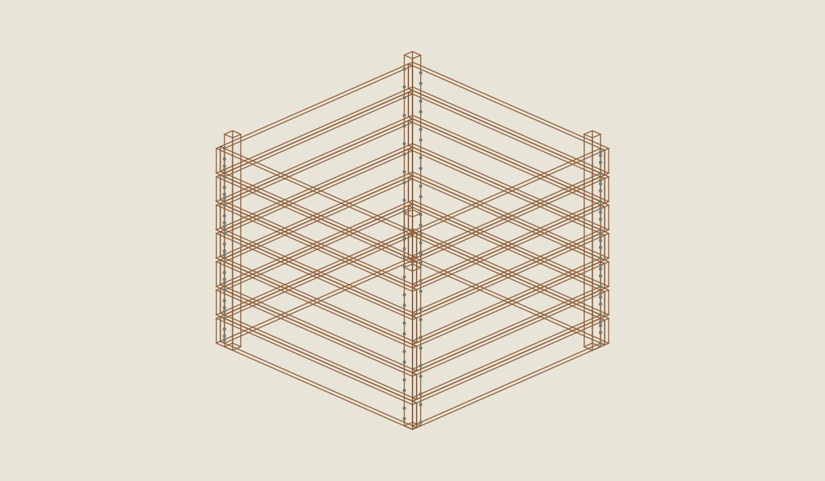
Loading the 3D view…
Drag to turn. Pinch or use + / − to zoom. The written step covers workholding and tool use.
Scroll or swipe the enlarged drawing to read its dimensions. Choose Fit to see the whole drawing again.
Slatted compost bin. Check the dimensions and build steps before cutting.
02 / Plan your build
Before you start
A compost bin should make the work easier to reach, not turn a useful pile into a difficult box. This design has four short corner posts and seven horizontal slats on each face. The front slats are screwed on individually, so they can be removed from the top down as the contents are taken out. There is no heavy hinged lid to hold overhead and no hardware hidden inside a permanently closed panel.
This is an open garden-trimming bin, not a rodent-resistant food-waste system. Its half-inch ventilation gaps, open top, and open ground contact are deliberate. Keep kitchen scraps, meat, dairy, manure, pet waste, diseased material, and seeded aggressive weeds out of this version. EPA's pest-exclusion guidance calls for an enclosure with much smaller openings; this bin does not meet that description.
Where it goes
Sheltered, firm, level ground with room to work in front. Keep it clear of fences so you can inspect the back slats, and away from drains, waterways, buildings, and elevated structures. It has no wind rating or ground anchor.
Footprint: 36 × 36 inches. Leave room to stand in front of the bin, where the slats come off.
What to expect
Intermediate beginner: repeatable panel layout and controlled screw placement. Plan 4–6 working hours.
A planning estimate for the hands-on work, once the materials are bought and the tools are set up. It has not been timed on a finished build.
Check the spot
- Sheltered, firm, level ground with room to work in front. Keep it clear of fences so you can inspect the back slats, and away from drains, waterways, buildings, and elevated structures. It has no wind rating or ground anchor.
- Measure the boards and hardware you actually bought before you cut, and set up a steady work surface. Keep other people back while you cut and drill.
Stop and check first if…
- Do not use this open bin for kitchen scraps, manure, pet waste, diseased material, or aggressive weeds carrying seeds.
- Stop for rocking, leaning, opening joints, split posts, or inaccessible slats.
- This is not a seat, climbing structure, animal enclosure, retaining wall, or roof support.
Work safely
- Have a tape, square, pencil, level, clamps, a saw and supported cutting station, drill/driver, countersink, suitable pilot/clearance bits, and the correct screw-driving bit. Make one half-inch spacing block and one full-height story stick from scrap. Wear appropriate eye, hearing, and dust protection. Keep clamps and stock supports clear of the cut path. Short scrap spacers are positioning aids, not pieces to hold beside a running blade.
- Do not use this open bin for kitchen scraps, manure, pet waste, diseased material, or aggressive weeds carrying seeds.
- Stop for rocking, leaning, opening joints, split posts, or inaccessible slats.
- This is not a seat, climbing structure, animal enclosure, retaining wall, or roof support.
Budget
We have not put a price on this one yet. Lumber and hardware prices change by store and season, so price the list under What you need at your local supplier before you buy.
03 / Gather and cut
What you need
Slat boards
10 boards
Sound untreated pine or Douglas-fir 1 × 4; actual 0.75 × 3.5 inches. Ten 10-foot boards.
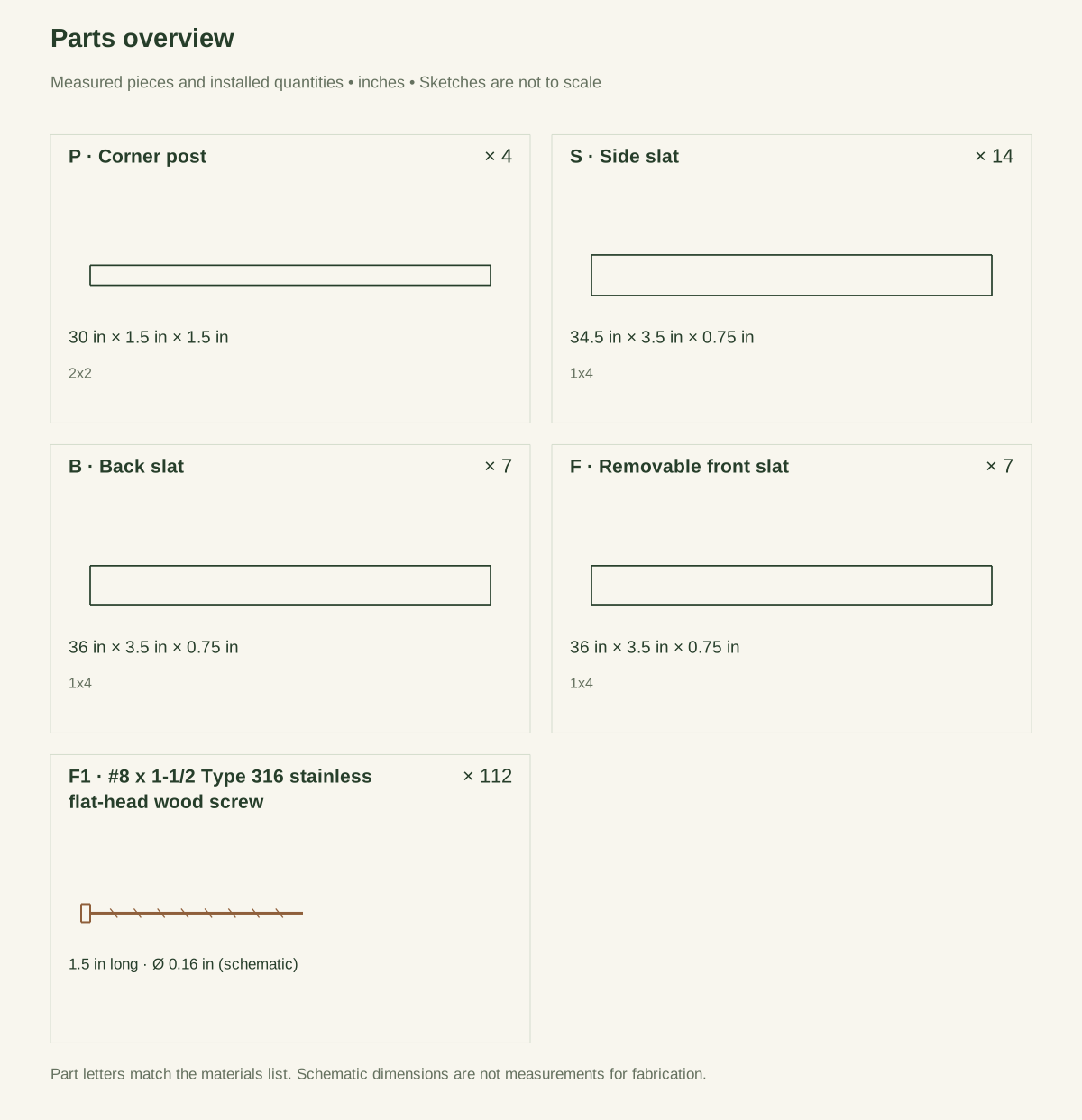
Supply fourteen S slats at 34.5 inches, seven B at 36 inches, and seven F at 36 inches, with saw kerf and spare stock.
Corner posts
2 boards
Sound untreated 2 × 2; actual 1.5 × 1.5 inches. Two 8-foot boards.
Cut four 30-inch posts. Reject splits or loose knots where the repeated screws enter.
Slat screws
112 screws
#8 × 1.5-inch Type 316 stainless flat-head wood screws. Packages containing at least 112 identical screws.
Four per slat × 28 slats. Confirm the selected product's pilot and edge-distance requirements; the front uses the same removable screws.
Abrasive paper
As needed consumable
80/120 grit as needed for hand-contact edges. Suitable small sheets or pack.
No glue, liner, cover, preservative, staples, or post anchorage is included.
Cut list
| Piece | How many | Cut length | Note |
|---|---|---|---|
| P — Corner post | 4 | 30 in | Part P, cut from 2x2. Size: 30 × 1.5 × 1.5 in. Check the plan sheets for its reference edges and any shaped detail. |
| S — Side slat | 14 | 34.5 in | Part S, cut from 1x4. Size: 34.5 × 3.5 × 0.75 in. Check the plan sheets for its reference edges and any shaped detail. |
| B — Back slat | 7 | 36 in | Part B, cut from 1x4. Size: 36 × 3.5 × 0.75 in. Check the plan sheets for its reference edges and any shaped detail. |
| F — Removable front slat | 7 | 36 in | Part F, cut from 1x4. Size: 36 × 3.5 × 0.75 in. Check the plan sheets for its reference edges and any shaped detail. |
Tools
- Tape or rule, square, and pencil
- Clamps and stable supported work surface
- Suitable saw with its required guarding
- Drill/driver, selected-product pilot and clearance bits, and countersink
- Abrasives for hand-contact edges
- Story stick for the seven 4-inch-pitch slat rows
- Receiving container and fork or shovel suited to garden trimmings
Protective gear
- Eye protection for cutting and drilling; match other protection to the actual tool instructions.
- Appropriate hearing protection and wood-dust control for the selected cutting method.
04 / Put it together
Build steps
- 01
Establish the dimensions before cutting repetitions
Measure the actual board thicknesses and post section. This plan uses 3/4-inch slats and 1-1/2-inch posts. If those measurements differ, update the corner geometry and screw lines; do not force a different section into the drawing. Cut one long and one short slat first, then verify their role around a dry-clamped corner.
Close-up · Whole model shows the complete part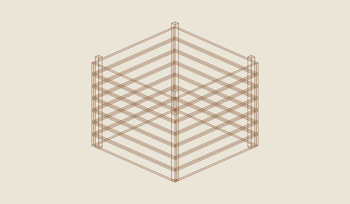
Loading the 3D view…
Drag to turn. Pinch or use + / − to zoom. The written step covers workholding and tool use.
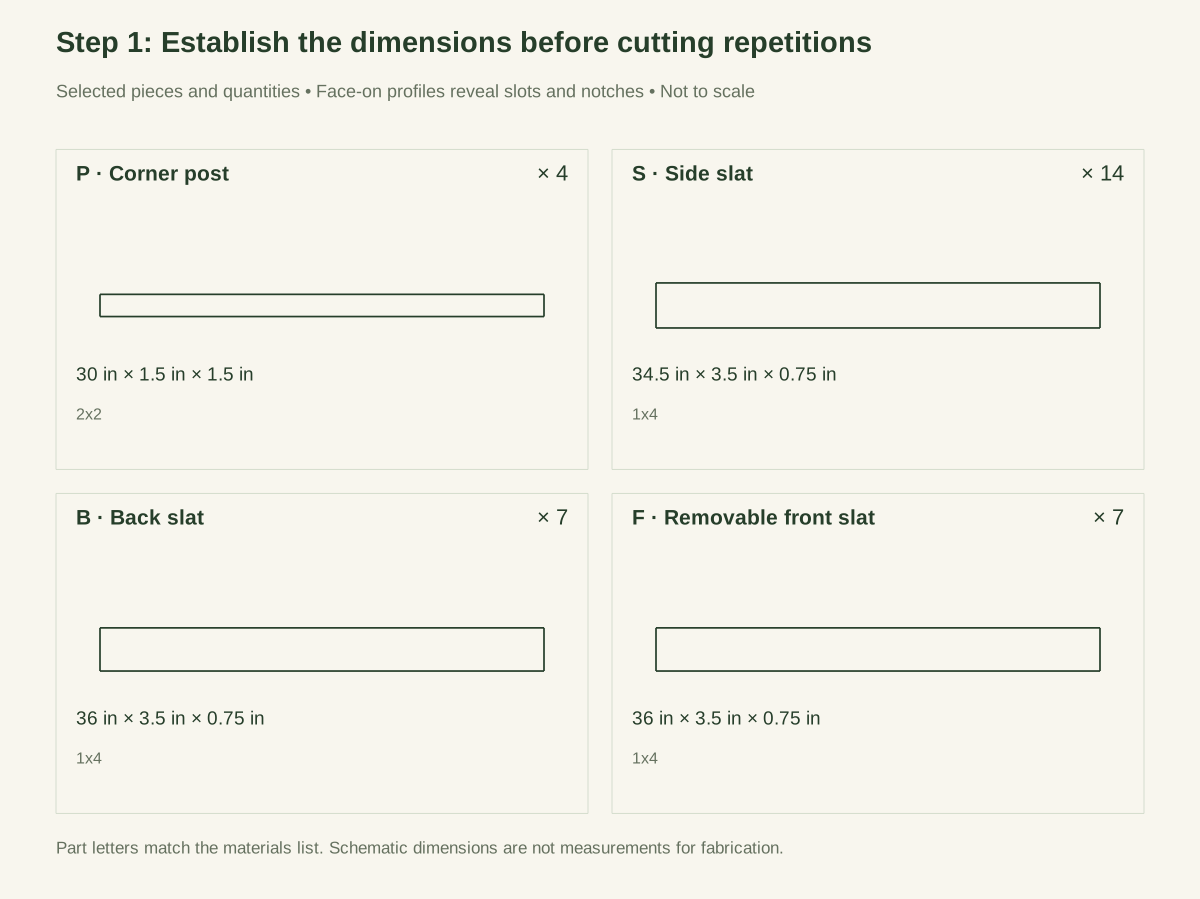
Scroll or swipe the enlarged drawing to read its dimensions. Choose Fit to see the whole drawing again.
Check: Confirm 3/4 × 3.5-inch slats and 1.5-inch-square posts before repetition.
- 02
Cut matching parts and mark their faces
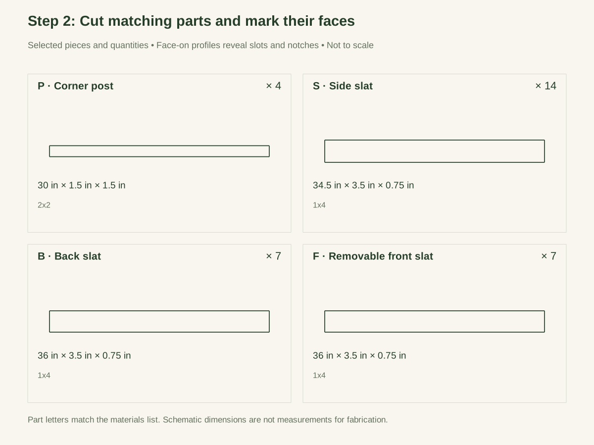
Cut the 28 slats and four posts. Compare pieces of the same group face to face; matching lengths should be within 1/32 inch. Mark the inside face and bottom end of each post. Ease cut edges but leave flat seating faces at the joints. Set aside any slat whose screw zone has a split or knot.
Close-up · Whole model shows the complete part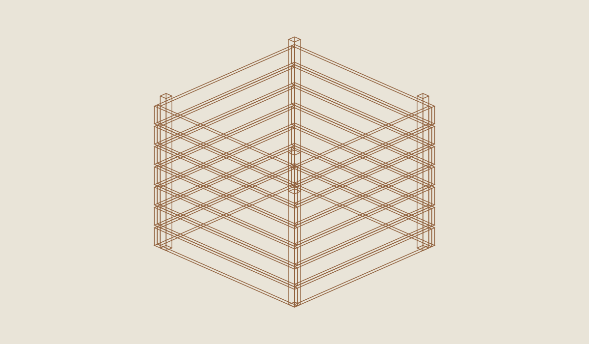
Loading the 3D view…
Drag to turn. Pinch or use + / − to zoom. The written step covers workholding and tool use.
Scroll or swipe the enlarged drawing to read its dimensions. Choose Fit to see the whole drawing again.
Check: Four 30-inch posts, fourteen 34.5-inch side slats, and fourteen 36-inch front/back slats are labeled.
- 03
Make a story stick for the seven rows
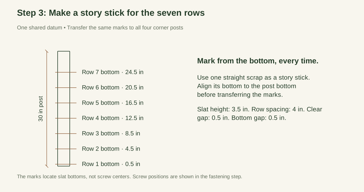
From the bottom of a 30-inch post, mark slat bottom elevations at 1/2, 4-1/2, 8-1/2, 12-1/2, 16-1/2, 20-1/2, and 24-1/2 inches. Each slat is 3-1/2 inches high; each gap is 1/2 inch. The last slat ends at 28, leaving 2 inches of post above it. Transfer every mark from this one story stick, not by accumulating seven separate measurements.
Close-up · Whole model shows the complete part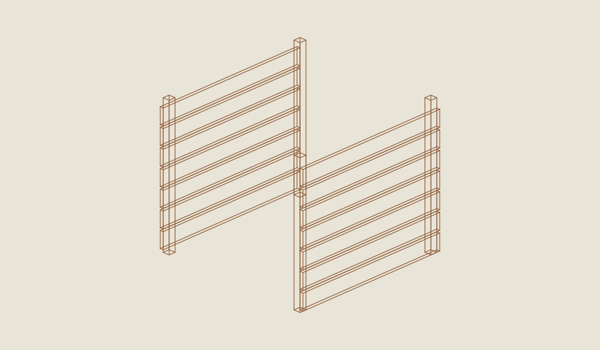
Loading the 3D view…
Drag to turn. Pinch or use + / − to zoom. The written step covers workholding and tool use.
Scroll or swipe the enlarged drawing to read its dimensions. Choose Fit to see the whole drawing again.
Mark slat bottoms on one story stick, then transfer the same marks to each post.
Check: The first row starts 0.5 inch above the base; seven rows follow a 4-inch pitch.
- 04
Assemble the two side panels
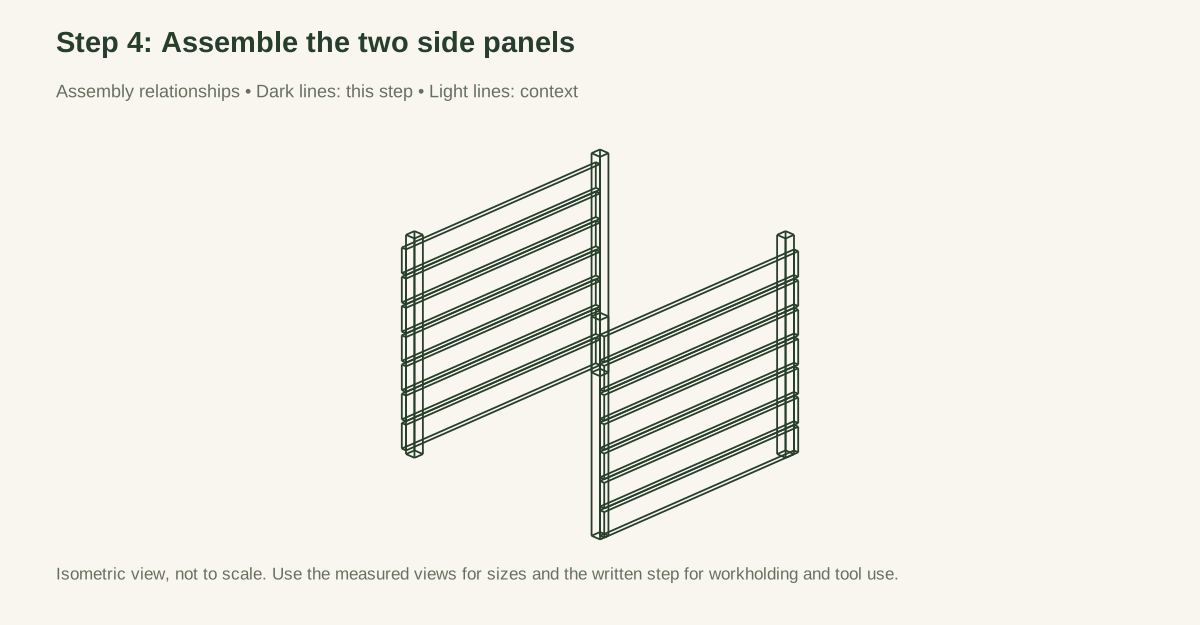
Lay two posts parallel on the bench, with their outside edges 34-1/2 inches apart. Place seven S slats across them, flush with the outside post edges. Their ends bear over the full 1-1/2-inch post width. Keep the lower row on the half-inch marks and use the spacer between rows.
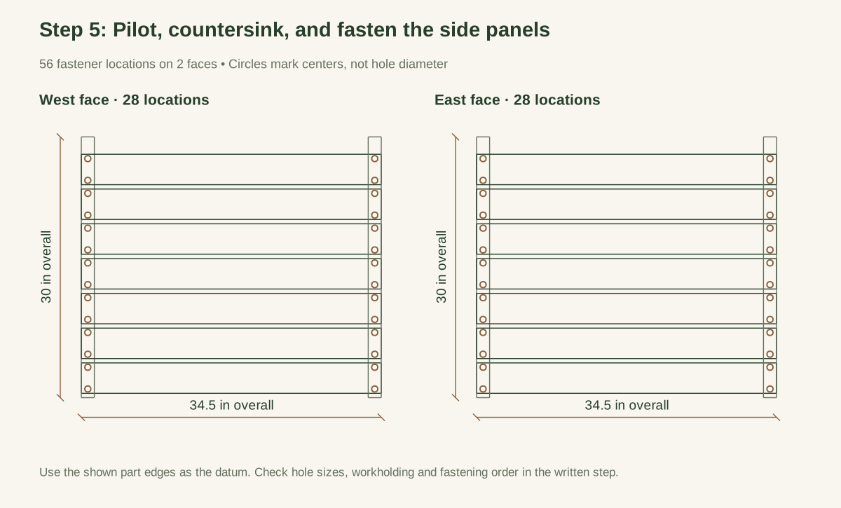
The screw line is 3/4 inch from each slat end. On every side slat, the two screws at an end are 1/2 and 3 inches above its bottom edge. Mark these positions before drilling. There are 14 side slats × 4 screws = 56 side-panel screws.
Close-up · Whole model shows the complete part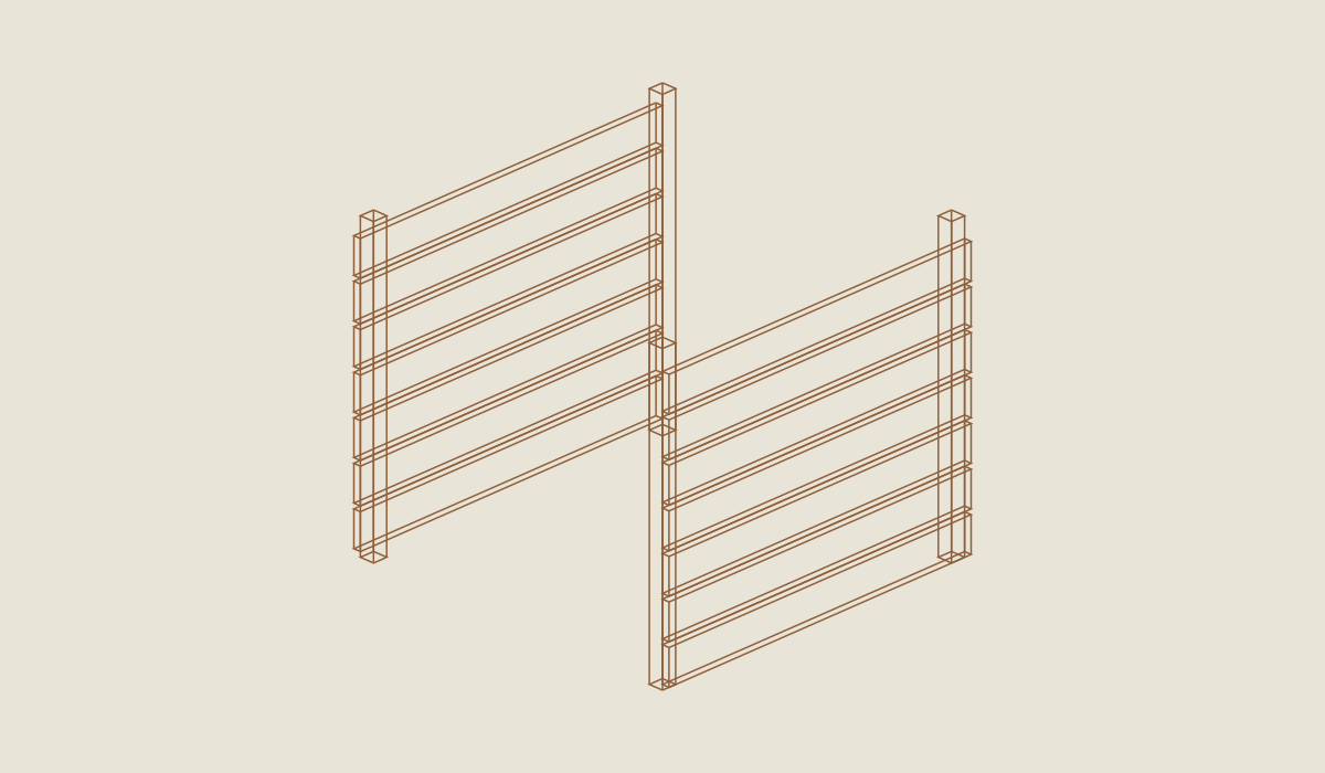
Loading the 3D view…
Drag to turn. Pinch or use + / − to zoom. The written step covers workholding and tool use.
Scroll or swipe the enlarged drawing to read its dimensions. Choose Fit to see the whole drawing again.
Make two matching sides. The front and back slats are not fitted yet.
Check: The two side panels match, with sound bearing at both slat ends.
- 05
Pilot, countersink, and fasten the side panels
For conventional #8 screws in this softwood geometry, trial a 7/64-inch receiving pilot with an 11/64-inch clearance hole through the slat only. Adjust to the actual screw instructions and scrap test; do not drill the larger clearance into the post. Countersink shallowly. Clamp each joint and seat heads flush with controlled torque. A split post or stripped hole needs repair or replacement, not another screw immediately beside it.
Measure the post-to-post separation again after fastening. A panel should lie flat without clamps forcing it against the bench. Build the second panel as a matching assembly, with the slats facing outward when erected.
Close-up · Whole model shows the complete part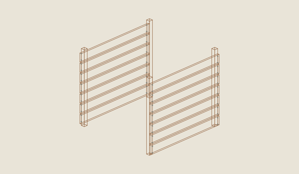
Loading the 3D view…
Drag to turn. Pinch or use + / − to zoom. The written step covers workholding and tool use.
Scroll or swipe the enlarged drawing to read its dimensions. Choose Fit to see the whole drawing again.
Side slats are 34.5 inches long. Each side has seven slats and 28 screw locations.
Check: Receiving pilots and through-slat clearance holes are distinct; no post splits or protruding screw points.
- 06
Join the sides with the back slats
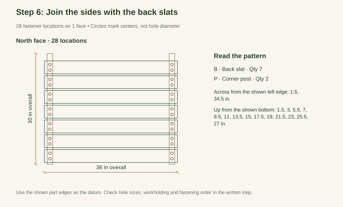
Stand the side panels upright with help. Their outer faces will be 36 inches apart once the 36-inch back spans them. The back slats overlap the side slat ends by 3/4 inch at each corner; do not place them between the sides.
On B slats, the vertical screw lines are 1-1/2 inches from each end. Screw heights are 1 and 2-1/2 inches above the slat bottom. This offsets them from the side screws inside the corner posts. Fit the bottom and top back slats first, then the middle rows. Install 28 back screws.
Close-up · Whole model shows the complete part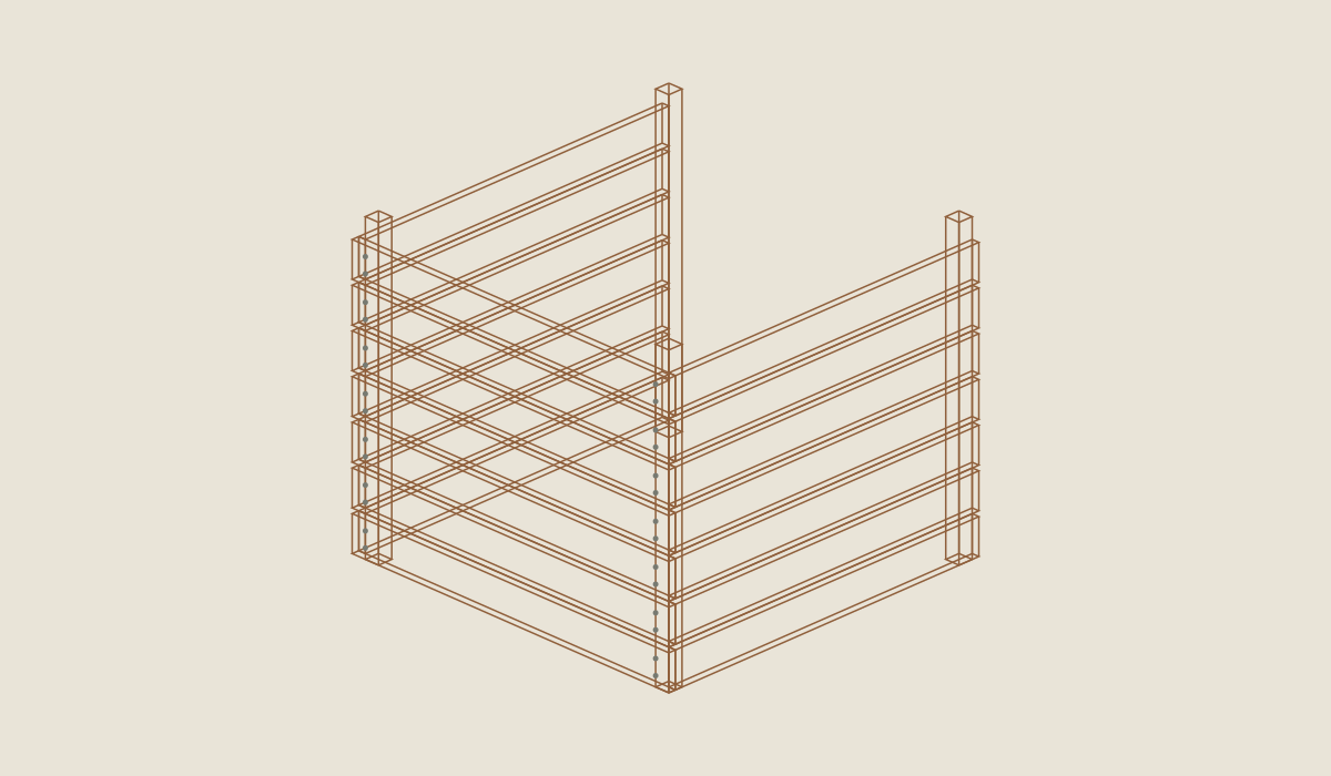
Loading the 3D view…
Drag to turn. Pinch or use + / − to zoom. The written step covers workholding and tool use.
Scroll or swipe the enlarged drawing to read its dimensions. Choose Fit to see the whole drawing again.
Use the 36-inch back slats here. Their screw heights are staggered from the side screws.
Check: Back slats run through the corners; do not interchange them with the 34.5-inch side pieces.
- 07
Square the footprint before closing the front
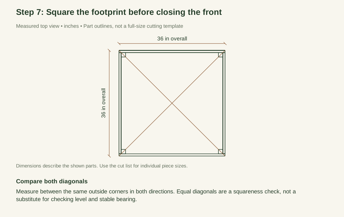
Set the three-sided assembly on a flat reference surface. Check the 36 × 36 outside footprint. The ideal outside diagonal is 36 × √2 = 50.912 inches; matching the two diagonals matters more than reading the final thousandth. Target a difference no greater than 1/8 inch without twisting the panels. Confirm each post stands upright and all four feet contact the surface.
Close-up · Whole model shows the complete part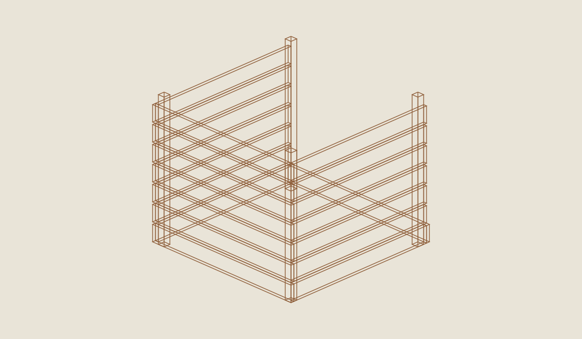
Loading the 3D view…
Drag to turn. Pinch or use + / − to zoom. The written step covers workholding and tool use.
Scroll or swipe the enlarged drawing to read its dimensions. Choose Fit to see the whole drawing again.
Hold one front slat in its final position without fastening it. Its outer face establishes the 36 × 36-inch footprint for the diagonal check. The slat shown pale in 3D is a temporary reference; fasten the front in the next step.
Check: The outside footprint is 36 × 36 inches and opposing diagonal measurements match.
- 08
Fit the removable front slats
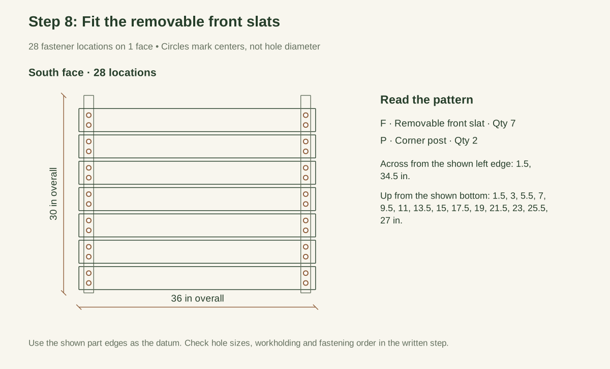
Fit F slats across the front with the same overhang, row elevations, screw lines, and screw heights as the back. Install 28 front screws. Do not glue this face. Number the slats F1 at the bottom through F7 at the top, and mark a small arrow showing the outward face. The full bin contains 112 installed screws.
Close-up · Whole model shows the complete part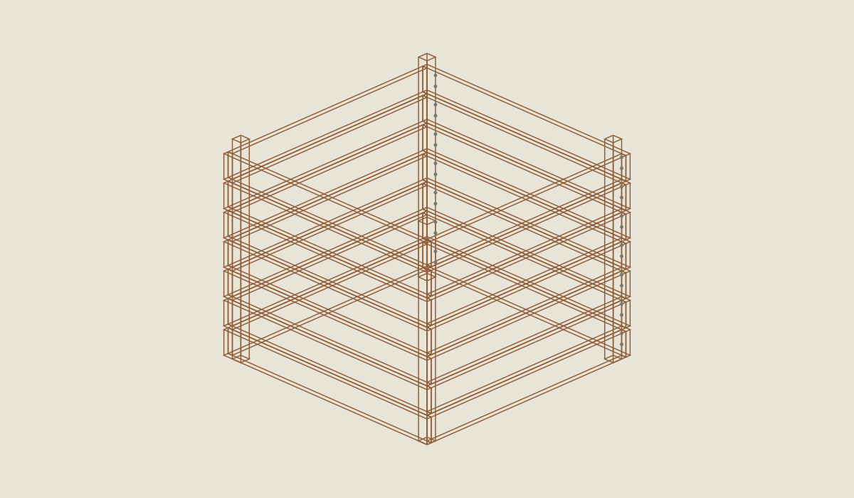
Loading the 3D view…
Drag to turn. Pinch or use + / − to zoom. The written step covers workholding and tool use.
Scroll or swipe the enlarged drawing to read its dimensions. Choose Fit to see the whole drawing again.
Screw on each front slat separately so it can later be removed.
Check: Each front slat remains individually removable; all 28 slats account for 112 screws.
- 09
Test access while the bin is empty
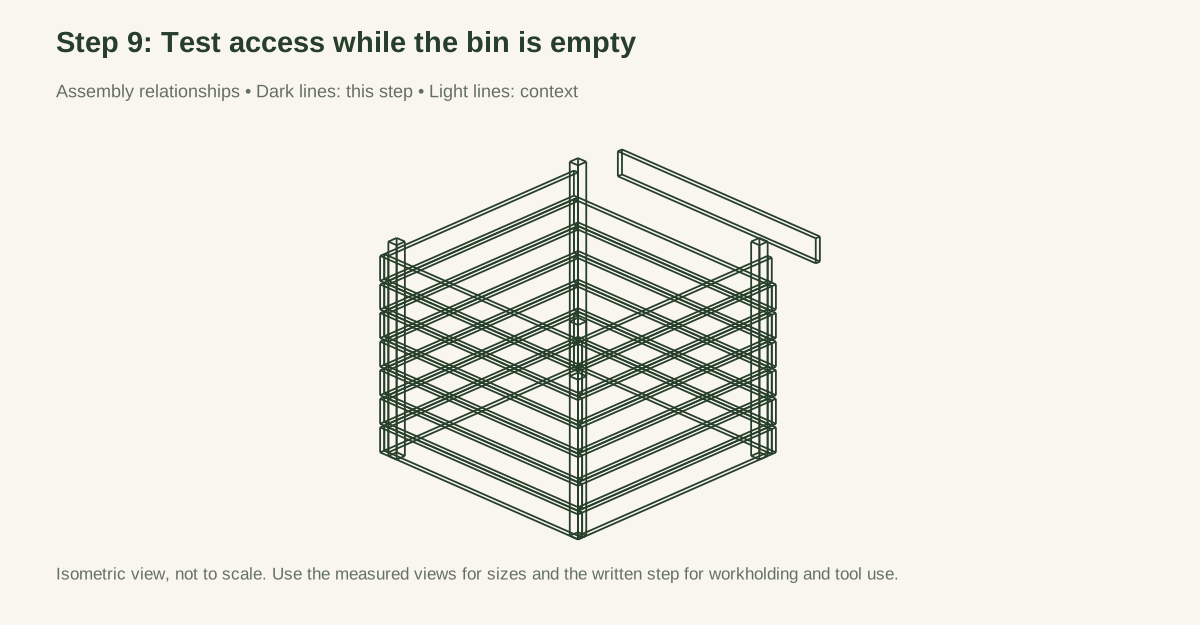
Remove F7, then refit it. Check that its screws can be reached with the driver and that no adjacent slat blocks the operation. Inspect the empty inside corners and post condition. A half-inch spacer should fit the ventilation gaps without levering the boards apart. Inspect the entire perimeter for proud heads, sharp splinters, and projecting points.
Close-up · Whole model shows the complete part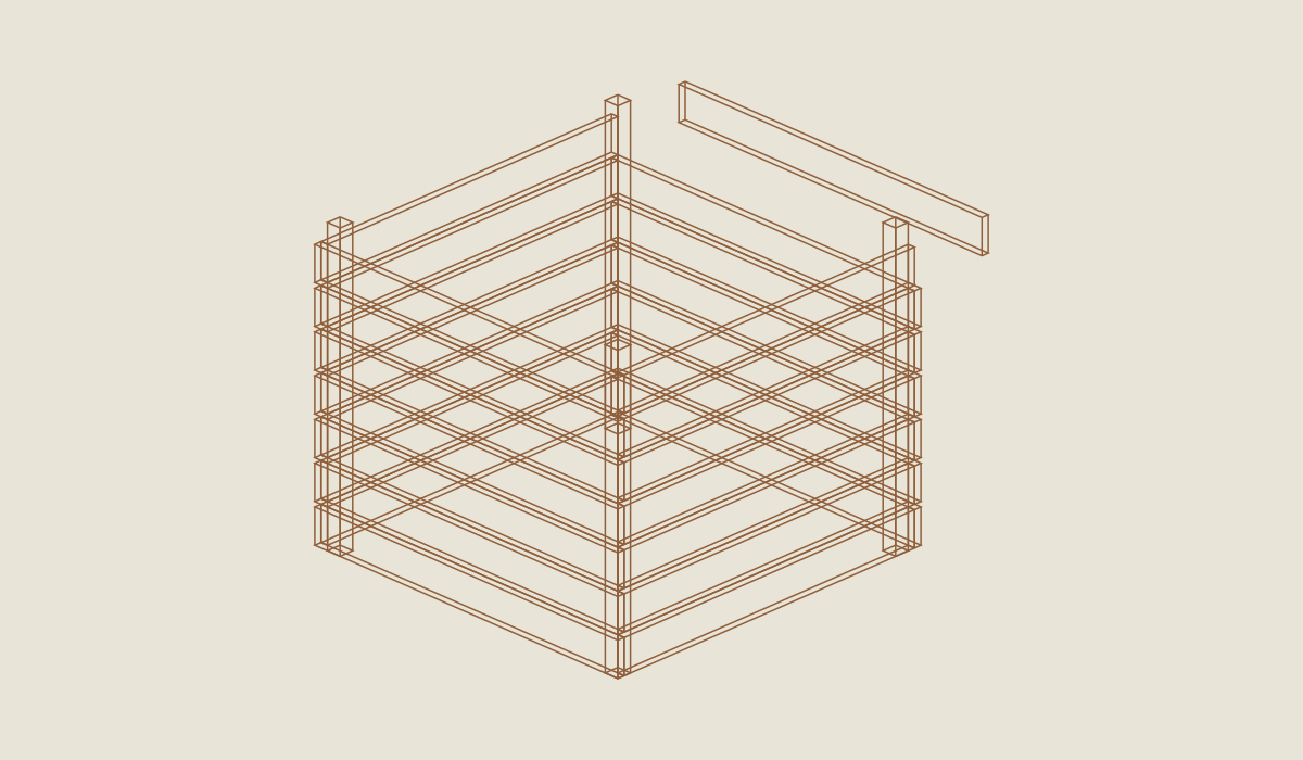
Loading the 3D view…
Drag to turn. Pinch or use + / − to zoom. The written step covers workholding and tool use.
Scroll or swipe the enlarged drawing to read its dimensions. Choose Fit to see the whole drawing again.
Empty-bin access check: remove only the upper front slat.
Check: Demonstrate top-down front removal while the bin is empty.
- 10
Move the empty assembly to its final position
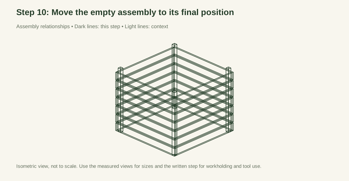
Use two people, lifting by the posts and lower framing rather than twisting a single top slat. Do not drag or move a filled bin. No excavation is designed here. If the site needs grading, anchors, utility work, or retaining, stop and resolve that separately. The bin must stand without rocking before any contents are added.
Close-up · Whole model shows the complete part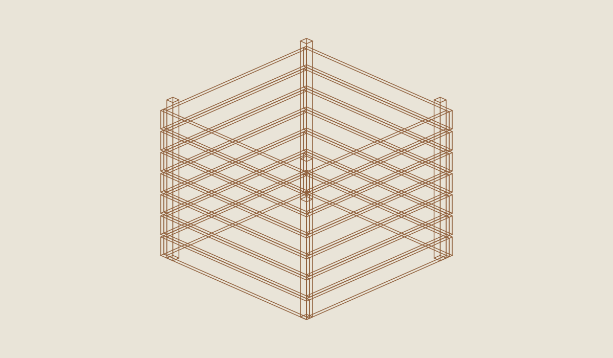
Loading the 3D view…
Drag to turn. Pinch or use + / − to zoom. The written step covers workholding and tool use.
Scroll or swipe the enlarged drawing to read its dimensions. Choose Fit to see the whole drawing again.
Placement reference only: move the empty bin, with help, to the checked level site.
Check: Every post bears on the intended level ground; no improvised loose wedges or anchors.
- 11
Start with appropriate garden material
Use clean garden trimmings and leaves, with no food scraps in this open version. Mix wetter green garden material with dry leaves or other appropriate browns. Keep the mixture airy and damp rather than compressed or saturated. CalRecycle's home-compost guidance explains the roles of carbon, nitrogen, air, and moisture; it does not validate this wood structure.
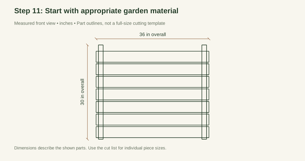
Keep material below the 27-inch line. Do not lean a loaded fork on the rim or tamp the pile with your feet. Observe the sides while adding the first material; stop for movement, opening joints, or unusual bowing.
Close-up · Whole model shows the complete part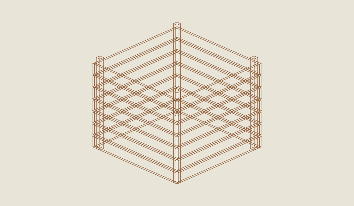
Loading the 3D view…
Drag to turn. Pinch or use + / − to zoom. The written step covers workholding and tool use.
Scroll or swipe the enlarged drawing to read its dimensions. Choose Fit to see the whole drawing again.
The open bin is for the garden materials named in the step, not rodent-proof food-waste storage.
Check: Use garden trimmings only and stay below the 27-inch contents line.
- 12
Remove material without releasing a loaded wall
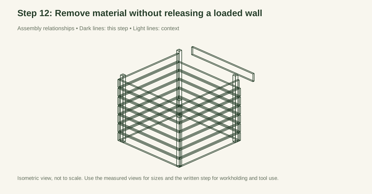
First lower the contents behind the top front slat, using the top opening. Only then remove that slat. Work down one slat at a time, lowering the pile below each slat before undoing it. Never remove the complete front while material is pushing against it. Refit each slat before filling the bin again. This access procedure is part of the design, not an optional precaution.
Close-up · Whole model shows the complete part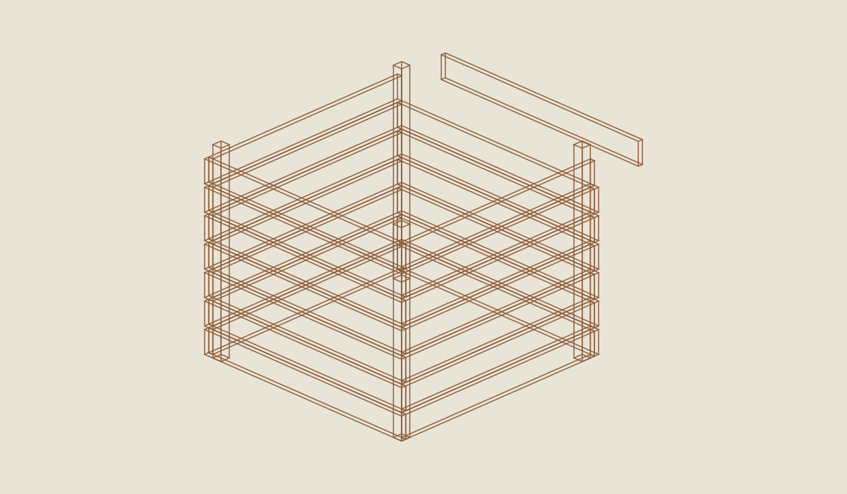
Loading the 3D view…
Drag to turn. Pinch or use + / − to zoom. The written step covers workholding and tool use.
Scroll or swipe the enlarged drawing to read its dimensions. Choose Fit to see the whole drawing again.
First lower the contents below a front slat; then remove that slat. Never release a loaded wall.
Check: Remove material pressure before loosening a front board; never release a loaded wall.
05 / Keep it sound
Care
After the build
- Keep the mixed garden-trimming contents below 27 inches. The bin’s volume is not a load rating.
- Rehearse front-board removal while empty, then unload the contents adjacent to a board before releasing it.
Check it each season
- Check the front screw holes whenever slats are removed. Inspect the feet and inside post faces at each emptying, and inspect the whole bin after prolonged wet weather. These are recommended triggers; no tested lifespan has been established. Replace deteriorated wood with the same section and recheck the relevant joints. Do not conceal soft posts behind a new decorative skin.
- Use the wire leaf cylinder to hold a separate supply of leaves. Once compost has genuinely matured, the compost screen can remove coarse pieces. Screening does not make immature or contaminated material safe.
If something looks wrong
- Sour, wet contents
- Check: Excess moisture or poor aeration. Fix: Stop watering, add suitable dry material, and turn without leaning on the bin.
- Pile stays cool
- Check: Size, moisture, material balance. Fix: Do not promise sanitation; review the compost process rather than overfilling.
- Front slat is difficult to remove
- Check: Material pressure or skewed screw. Fix: Lower contents first; never pry the loaded face outward.
- Repeatedly loose front screw
- Check: Worn hole or soft post. Fix: Unload and replace the damaged receiving component.
- Fresh gap at a corner
- Check: Split post or distorted ground support. Fix: Stop filling, unload safely, and correct the failure before reuse.
Keep exploring