Garden storage · Guide 87
How to Build a Seed-Packet Organizer with Removable Dividers
Build a small indoor seed sorter with four compartments and a lift-out cross-divider fitted to the actual thickness of your plywood.
01 / See the shape
View the project
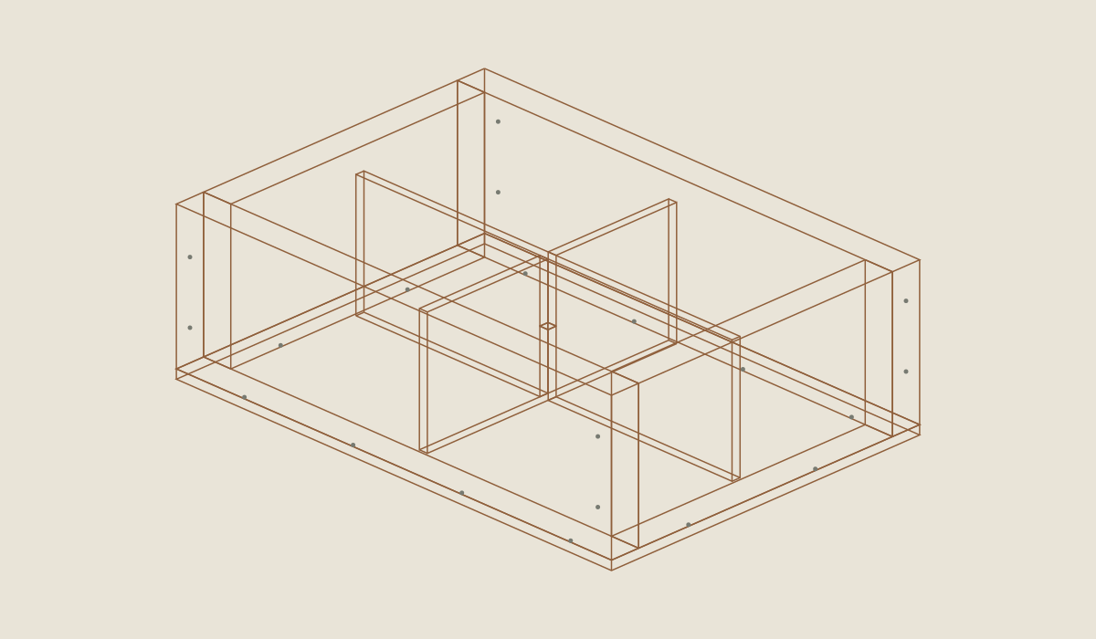
Loading the 3D view…
Drag to turn. Pinch or use + / − to zoom. The written step covers workholding and tool use.
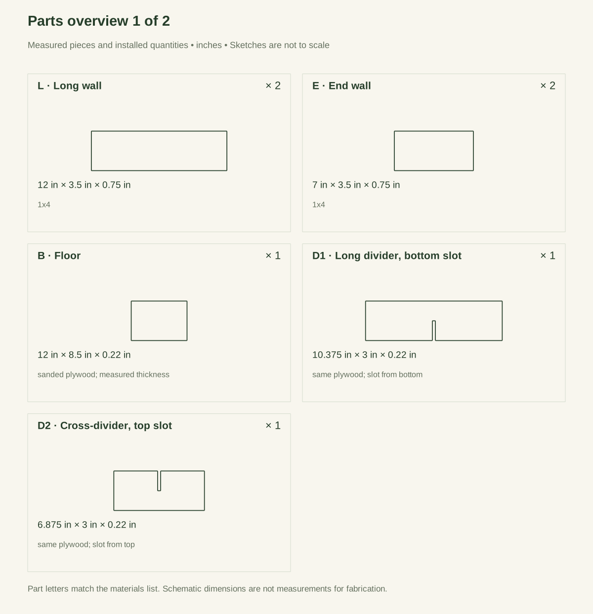
Scroll or swipe the enlarged drawing to read its dimensions. Choose Fit to see the whole drawing again.
Seed-packet organizer. Check the dimensions and build steps before cutting.
02 / Plan your build
Before you start
An organizer earns its place by making packets easy to find and old stock easy to notice. This one is a shallow wooden box with a removable cross-divider. The four bays can separate current sowing, later sowing, saved seed, and packets that need checking. Lift the divider out when a packet tears, a label falls behind it, or the box needs cleaning.
This is a sorting box for a dry indoor work area, not a moisture-controlled seed bank. It has no sealed lid, refrigeration, desiccant system, or pest-proof claim. University of Minnesota Extension recommends keeping seed cool and dry in tightly sealed containers; a wooden sorter does not replace that separate storage arrangement.
Where it goes
Dry indoor storage with the individual seed-packet temperature, moisture, and safety instructions followed. Not a humidity-controlled or weatherproof container.
Footprint: 12 × 8-1/2 inches.
What to expect
Beginner box with a precise opposing-slot divider detail. Plan 90–150 working minutes.
A planning estimate for the hands-on work, once the materials are bought and the tools are set up. It has not been timed on a finished build.
Check the spot
- Dry indoor storage with the individual seed-packet temperature, moisture, and safety instructions followed. Not a humidity-controlled or weatherproof container.
- Measure the boards and hardware you actually bought before you cut, and set up a steady work surface. Keep other people back while you cut and drill.
Stop and check first if…
- Do not force the cross-divider when the slots bind; support and refit the slot rather than bending the plywood.
- Stop for exposed floor-screw tips, split thin stock, damp packets, or unverified pesticide contamination.
- No sealed lid, loose desiccant, insect-proofing, weatherproofing, or seed-viability guarantee is included.
- Do not lift the loaded box by the removable divider; keep it supported from underneath when you move it.
Work safely
- Use a rule, square, pencil, clamps, supported saw, fine-tooth coping saw or another safely controlled slotting tool, drill/driver, countersink, suitable bits, and fine abrasives. Thin divider strips must be supported during cutting; do not try to hold a narrow strip beside an exposed powered blade. Clamp stock for drilling as well as sawing. OSHA's woodworking guidance identifies unsecured stock and hands near cutting tools as hazards, not acceptable shortcuts for small parts.
- Use appropriate eye, hearing, and dust protection. Mark the two divider slots clearly before cutting: one begins at the bottom, the other at the top. No soil preparation, excavation, wall anchoring, electrical work, or moisture-control installation is included.
- Do not force the cross-divider when the slots bind; support and refit the slot rather than bending the plywood.
- Stop for exposed floor-screw tips, split thin stock, damp packets, or unverified pesticide contamination.
- No sealed lid, loose desiccant, insect-proofing, weatherproofing, or seed-viability guarantee is included.
- Do not lift the loaded box by the removable divider; keep it supported from underneath when you move it.
Budget
We have not put a price on this one yet. Lumber and hardware prices change by store and season, so price the list under What you need at your local supplier before you buy.
03 / Gather and cut
What you need
Wall stock
1 board
Straight untreated pine 1 × 4; actual 0.75 × 3.5 inches. One 4-foot board.
Two 12-inch L walls and two 7-inch E walls use 38 inches plus kerf and trimming.
Floor and divider panel
1 panel
Sound sanded plywood; actual reference thickness 0.220 inch. Blank at least 18 × 13 inches after trimming, or a larger verified panel.
Cut the 12 × 8.5-inch floor, 10.375 × 3-inch D1, and 6.875 × 3-inch D2. Slots must match measured material, not a nominal 1/4-inch label.
Corner screws
8 screws
#6 × 1.5-inch stainless flat-head wood screws. Package of at least eight.
For the wall corners only. Confirm pilot and end-distance instructions on the selected product.
Floor screws
12 screws
#6 × 0.75-inch stainless flat-head wood screws. Package of at least twelve.
Use the shorter screws at the floor and inspect for protruding points.
Labels
As needed labels
Removable index cards or adhesive paper labels. Enough for the four compartments.
No glue, finish, permanent divider fastening, hinges, magnetic latch, liner, or loose silica gel is part of the design.
Cut list
| Piece | How many | Cut length | Note |
|---|---|---|---|
| L — Long wall | 2 | 12 in | Part L, cut from 1x4. Size: 12 × 3.5 × 0.75 in. Check the plan sheets for its reference edges and any shaped detail. |
| E — End wall | 2 | 7 in | Part E, cut from 1x4. Size: 7 × 3.5 × 0.75 in. Check the plan sheets for its reference edges and any shaped detail. |
| B — Floor | 1 | 12 in | Part B, cut from sanded plywood; measured thickness. Size: 12 × 8.5 × 0.22 in. Check the plan sheets for its reference edges and any shaped detail. |
| D1 — Long divider, bottom slot | 1 | 10.375 in | Part D1, cut from same plywood; slot from bottom. Size: 10.375 × 3 × 0.22 in. Check the plan sheets for its reference edges and any shaped detail. |
| D2 — Cross-divider, top slot | 1 | 6.875 in | Part D2, cut from same plywood; slot from top. Size: 6.875 × 3 × 0.22 in. Check the plan sheets for its reference edges and any shaped detail. |
Tools
- Tape or rule, square, and pencil
- Clamps and stable supported work surface
- Suitable saw with its required guarding
- Drill/driver, selected-product pilot and clearance bits, and countersink
- Abrasives for hand-contact edges
- Fine-tooth supported slotting tool
- Caliper or measured trial slot for the actual thin panel
Protective gear
- Eye protection for cutting and drilling; match other protection to the actual tool instructions.
- Appropriate hearing protection and wood-dust control for the selected cutting method.
04 / Put it together
Build steps
- 01
Measure stock and choose the inside faces
Check wall thickness, panel thickness, and flatness. This plan uses 3/4-inch walls and a 0.220-inch panel. If your panel is not 0.220 inch thick, the floor height becomes 3.5 inches plus the measured panel thickness, and both divider slots must match the new panel. Do not leave a 0.230-inch slot label attached to a different sheet. Mark the inside faces and lower edges of all four walls.
Close-up · Whole model shows the complete part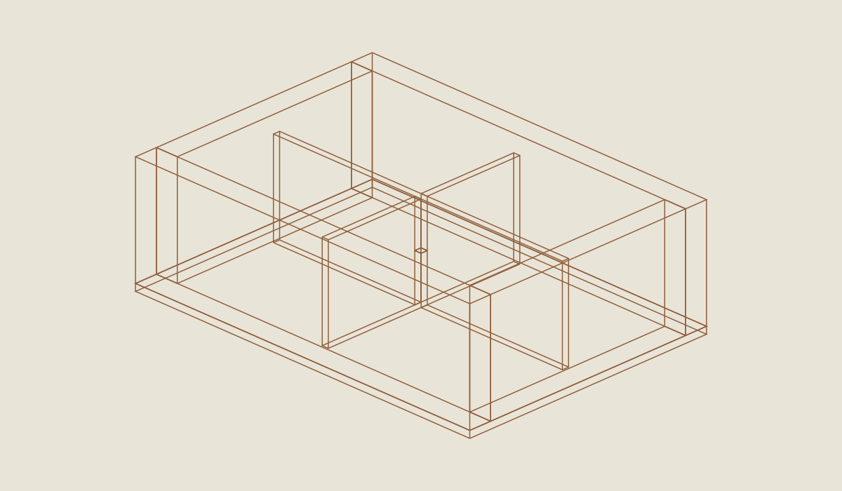
Loading the 3D view…
Drag to turn. Pinch or use + / − to zoom. The written step covers workholding and tool use.
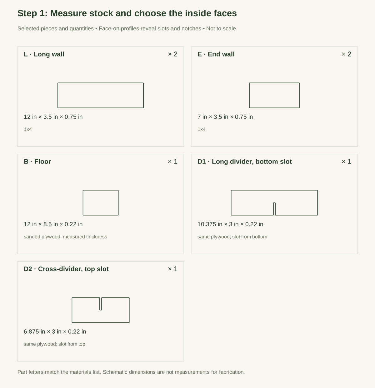
Scroll or swipe the enlarged drawing to read its dimensions. Choose Fit to see the whole drawing again.
Check: Actual wall and panel thicknesses are recorded; the slot width is based on this panel, not an unchanged reference number.
- 02
Cut the walls and floor
Cut two 12-inch L pieces, two 7-inch E pieces, and B at 12 × 8-1/2. Match like pieces within 1/32 inch as a proposed shop target and keep ends square. Remove splinters without rounding the joint seating faces. Reject a floor with loose plies, a bowed middle, or an exposed sharp veneer edge.
Close-up · Whole model shows the complete part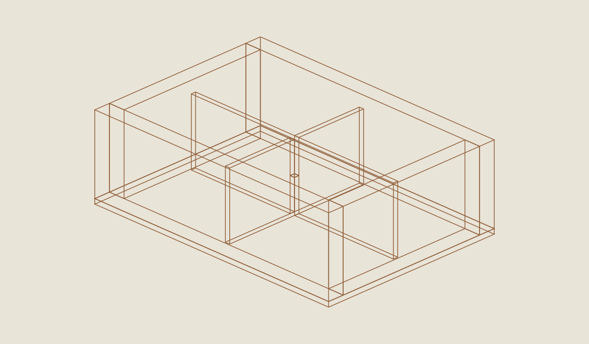
Loading the 3D view…
Drag to turn. Pinch or use + / − to zoom. The written step covers workholding and tool use.
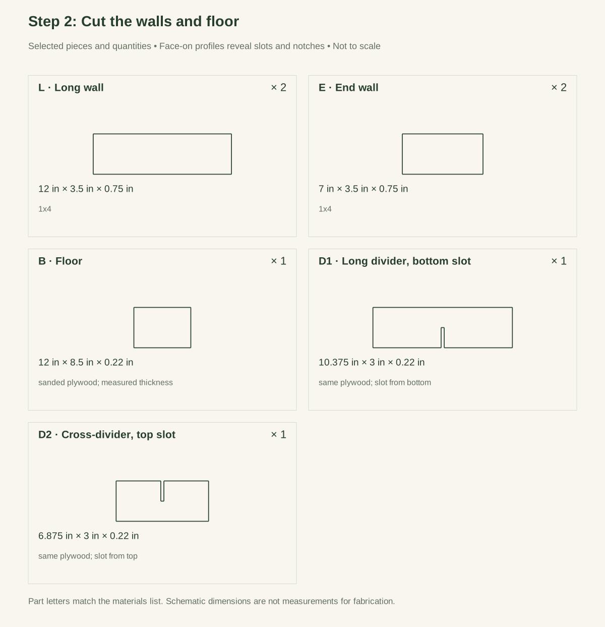
Scroll or swipe the enlarged drawing to read its dimensions. Choose Fit to see the whole drawing again.
Check: Two long walls, two ends and the thin floor match the cut list with square ends and sound edges.
- 03
Dry-clamp the wall ring
Fit E between L, with all bottoms on one flat surface. Check the 12 × 8-1/2 outside plan and 10-1/2 × 7 inside opening. Compare the diagonals; the ideal outside diagonal is √216.25 = 14.705 inches. Target a diagonal difference within 1/16 inch without twisting the assembly. Fit B underneath to confirm aligned outside edges before drilling.
Close-up · Whole model shows the complete part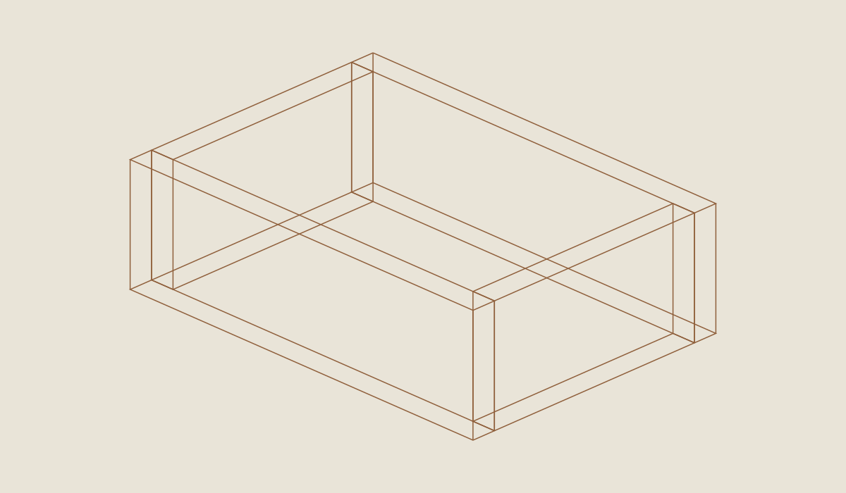
Loading the 3D view…
Drag to turn. Pinch or use + / − to zoom. The written step covers workholding and tool use.
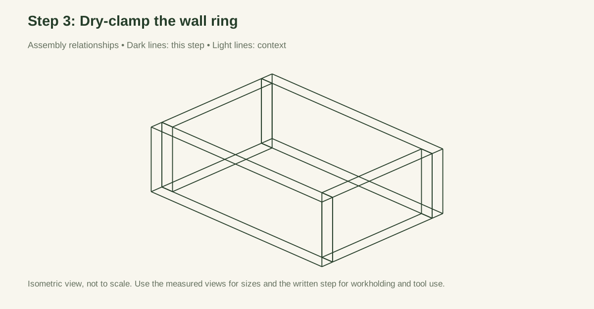
Scroll or swipe the enlarged drawing to read its dimensions. Choose Fit to see the whole drawing again.
Check: Wall ring and floor edges align; diagonal measurements agree without forcing the thin panel.
- 04
Mark the corner screws
On each L outside face, put screw lines 3/8 inch from each end. Mark holes 1 and 2-1/2 inches above the wall bottom. Each screw passes through L into E's end grain. That makes two screws at four corners: eight F1 screws.
Close-up · Whole model shows the complete part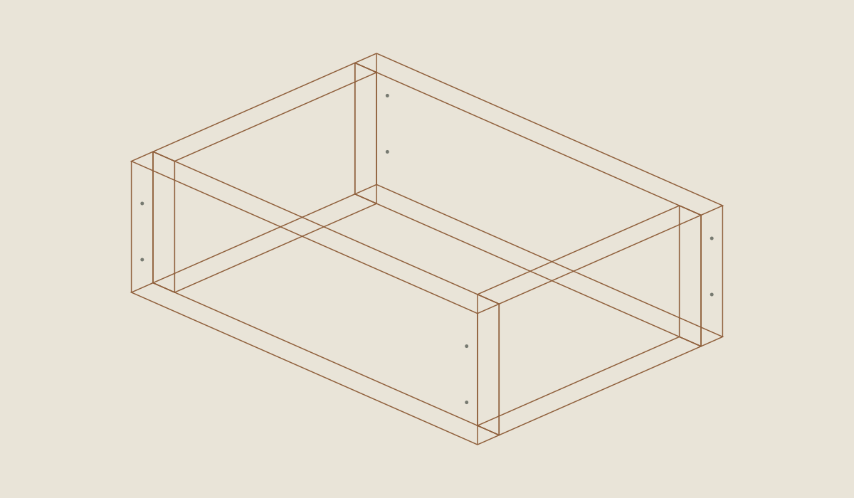
Loading the 3D view…
Drag to turn. Pinch or use + / − to zoom. The written step covers workholding and tool use.
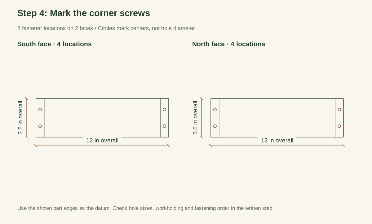
Scroll or swipe the enlarged drawing to read its dimensions. Choose Fit to see the whole drawing again.
Check: Eight corner screw stations lie in receiving end wood and clear the future floor screws.
- 05
Drill and fasten the corners
For a conventional #6 screw in this pine, trial a 5/64-inch receiving pilot and 9/64-inch clearance through L only, subject to the actual fastener's instructions. Countersink lightly and keep the joint clamped. Drive heads flush with controlled torque. If a split develops or a hole strips, replace the damaged receiving material rather than adding a screw beside it.
Close-up · Whole model shows the complete part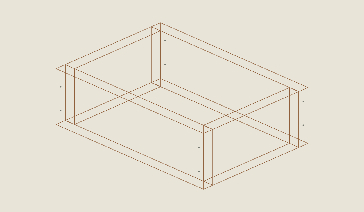
Loading the 3D view…
Drag to turn. Pinch or use + / − to zoom. The written step covers workholding and tool use.
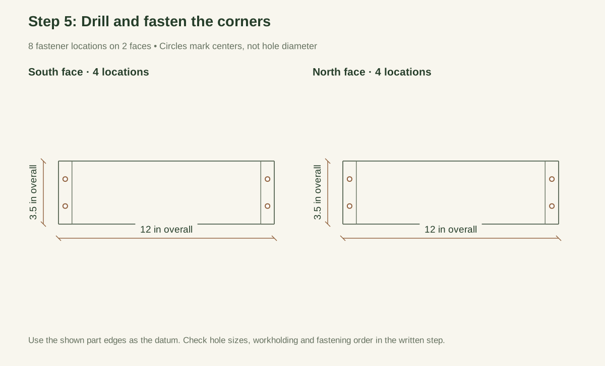
Scroll or swipe the enlarged drawing to read its dimensions. Choose Fit to see the whole drawing again.
Check: The eight body screws seat with no split or opening corner after clamps release.
- 06
Mark the twelve floor connections
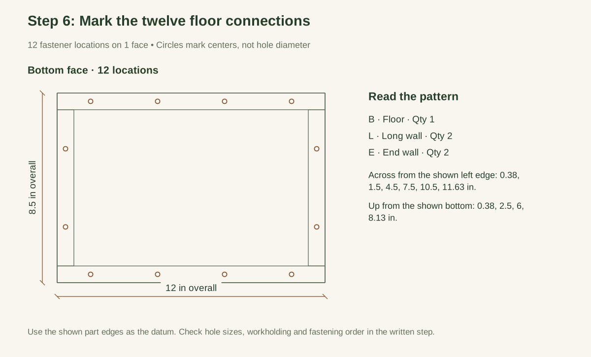
Invert the ring and clamp B beneath it. On lines 3/8 inch from the long floor edges, use x stations 1-1/2, 4-1/2, 7-1/2, and 10-1/2 inches: eight holes. On lines 3/8 inch from the short edges, use y stations 2-1/2 and 6 inches: four more. Every hole must align with a wall's lower edge, not the open interior.
Close-up · Whole model shows the complete part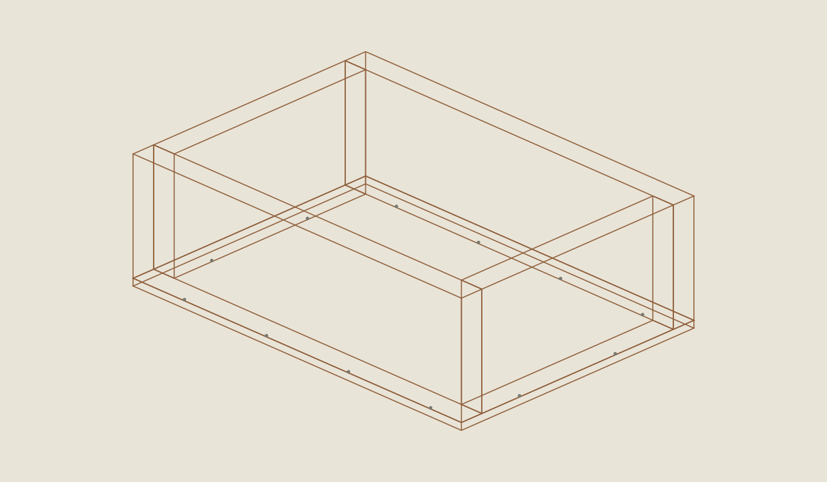
Loading the 3D view…
Drag to turn. Pinch or use + / − to zoom. The written step covers workholding and tool use.
Scroll or swipe the enlarged drawing to read its dimensions. Choose Fit to see the whole drawing again.
Check: Twelve floor fixing centers follow the lower wall edges rather than the hollow center.
- 07
Attach the thin floor carefully
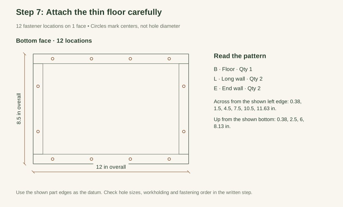
Drill clearance through B and controlled receiving pilots into the wall edges. Do not use a deep countersink that removes most of the thin panel. Seat the twelve F2 short screws just flush. Keep the two screw lengths separate: the floor uses 3/4-inch screws, not the 1-1/2-inch corner screws. Set the box upright and check for rocking or a bowed floor before making the divider.
Close-up · Whole model shows the complete part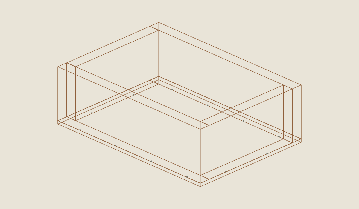
Loading the 3D view…
Drag to turn. Pinch or use + / − to zoom. The written step covers workholding and tool use.
Scroll or swipe the enlarged drawing to read its dimensions. Choose Fit to see the whole drawing again.
Check: All twelve floor screws seat without splitting the thin panel or protruding; the box rests flat.
- 08
Cut and label D1 and D2
Cut D1 at 10-3/8 × 3 and D2 at 6-7/8 × 3 from the same panel. Mark D1's bottom and D2's top with arrows. Check that each divider can enter the actual box without scraping both ends; do not shorten only one end so much that the cross becomes noticeably off-center.
Close-up · Whole model shows the complete part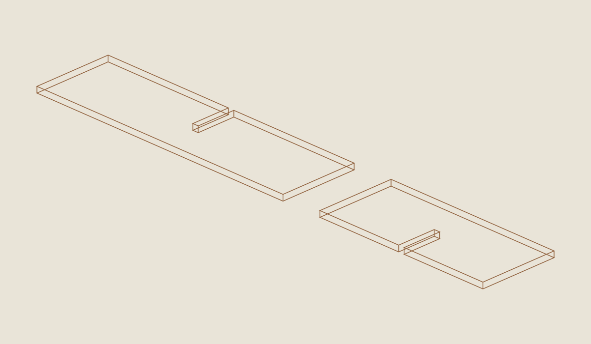
Loading the 3D view…
Drag to turn. Pinch or use + / − to zoom. The written step covers workholding and tool use.
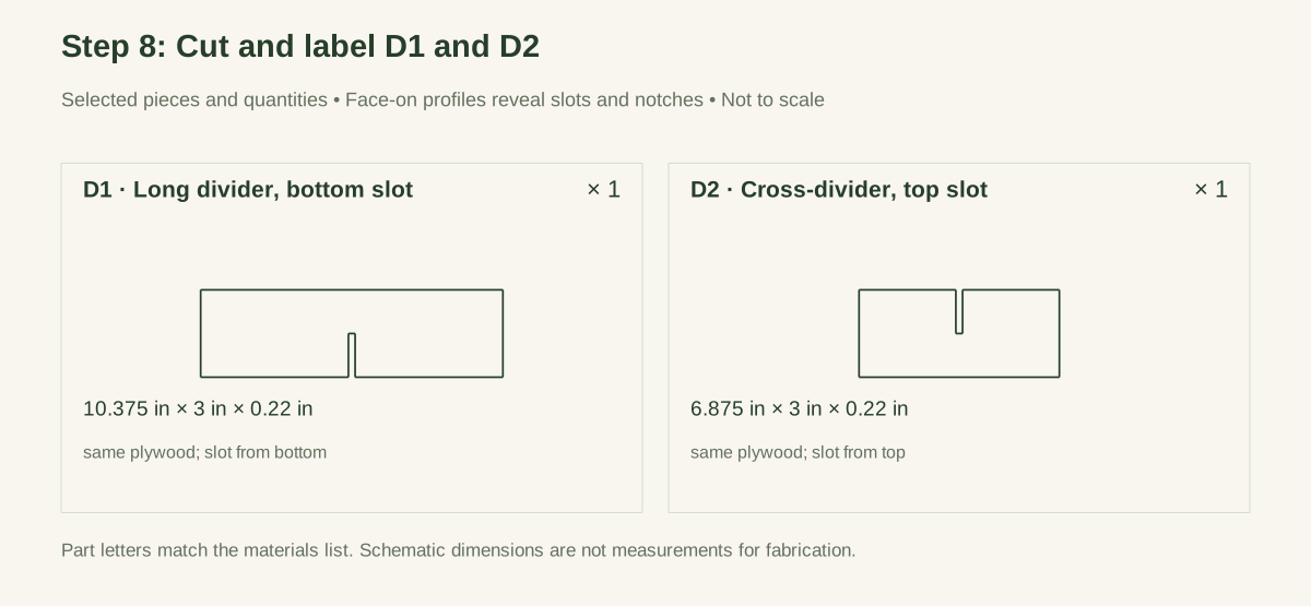
Scroll or swipe the enlarged drawing to read its dimensions. Choose Fit to see the whole drawing again.
Loose divider pieces: spacing is illustrative, not an assembly dimension.
Check: The two dividers are labeled and individually fit the real inside length/width with slight clearance.
- 09
Lay out the opposing half-laps
Mark D1's center 5-3/16 inches from an end and D2's center 3-7/16 inches from an end. Center each slot on that line. For the reference panel, the slot is 0.230 inch wide—0.010 inch wider than the measured 0.220 panel—pending a scrap-fit check.
D1's slot rises 1-1/2 inches from its bottom. D2's slot descends 1-1/2 inches from its top. Do not cut both from the same edge. The two half-depth cuts are what let the assembled divider bottoms and tops align.
Close-up · Whole model shows the complete part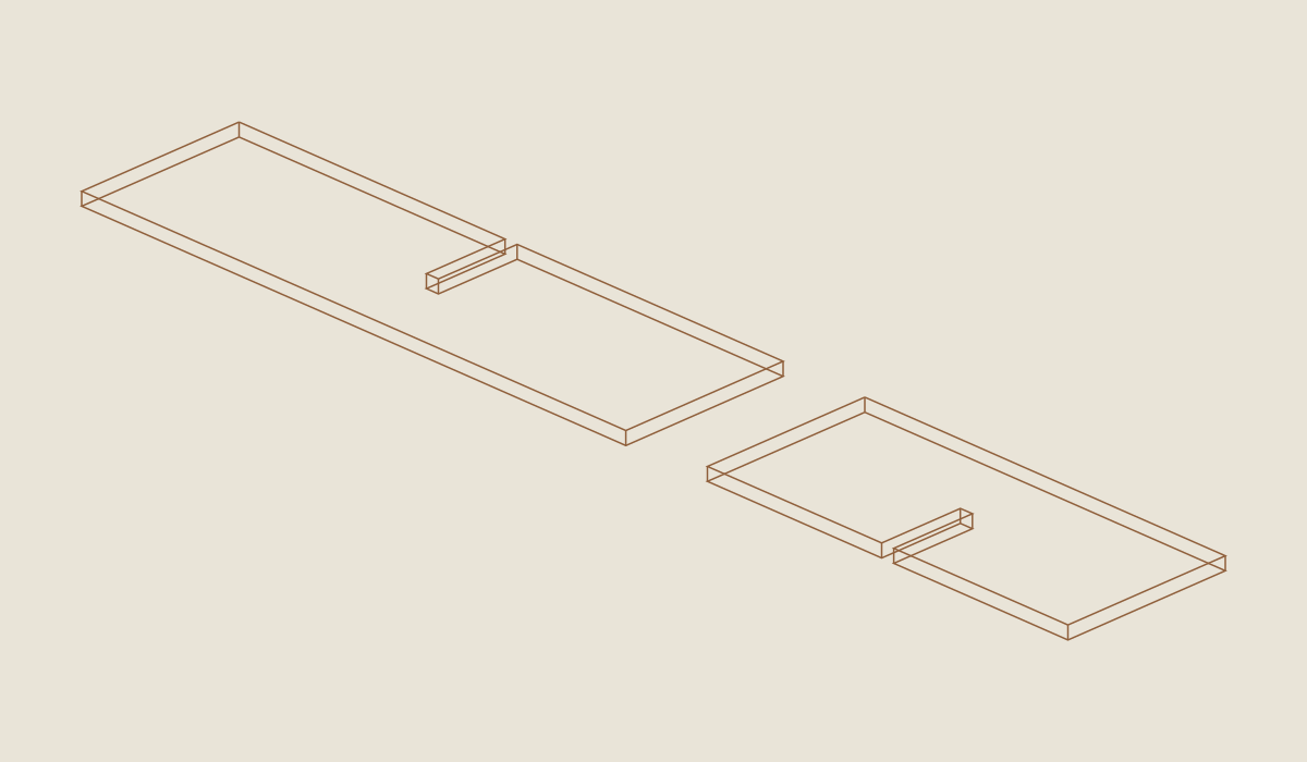
Loading the 3D view…
Drag to turn. Pinch or use + / − to zoom. The written step covers workholding and tool use.
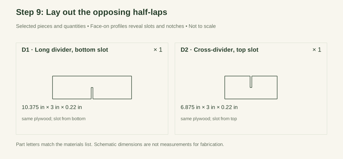
Scroll or swipe the enlarged drawing to read its dimensions. Choose Fit to see the whole drawing again.
One half-lap opens upward; the mating half-lap opens downward. The profiles are shown separately to make both cuts visible.
Check: The opposing center slots start on different edges and each stops at half the divider height.
- 10
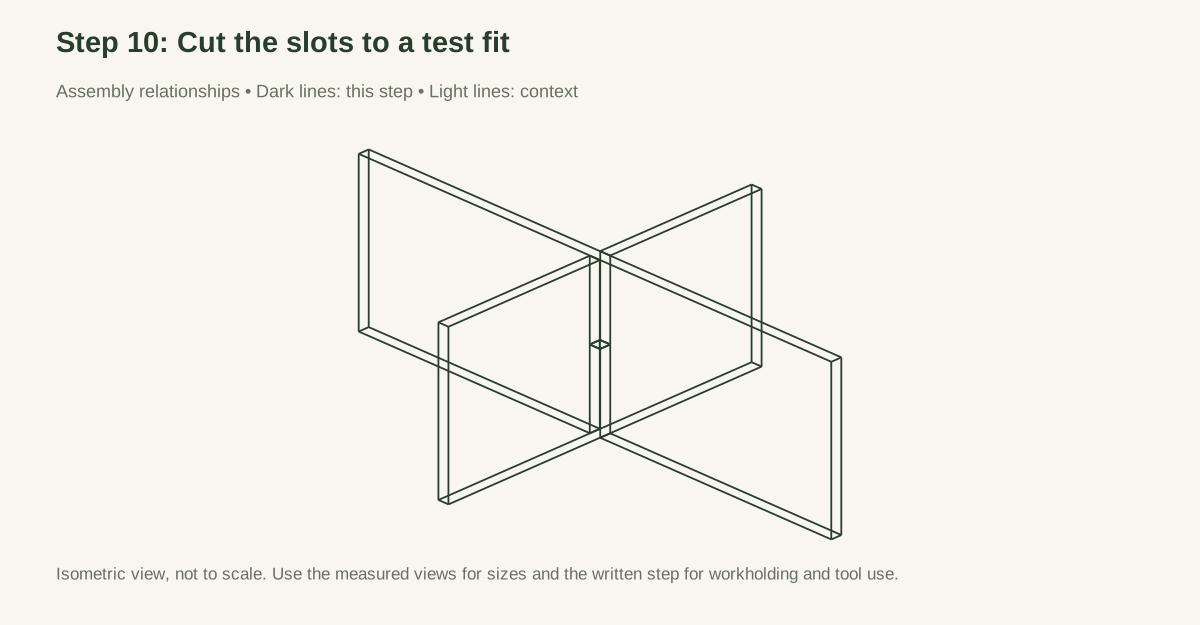
Cut the slots to a test fit
Clamp each strip against a backing piece, with the intended waste clear of the support. Cut just inside the marked slot sides, remove the small waste, and bring the opening to fit with a safe hand tool or abrasive. Test against an offcut of the actual sheet, not a nominal quarter-inch spacer. The joint should slide together without hammering, splitting, or a loose rocking fit.
Close-up · Whole model shows the complete part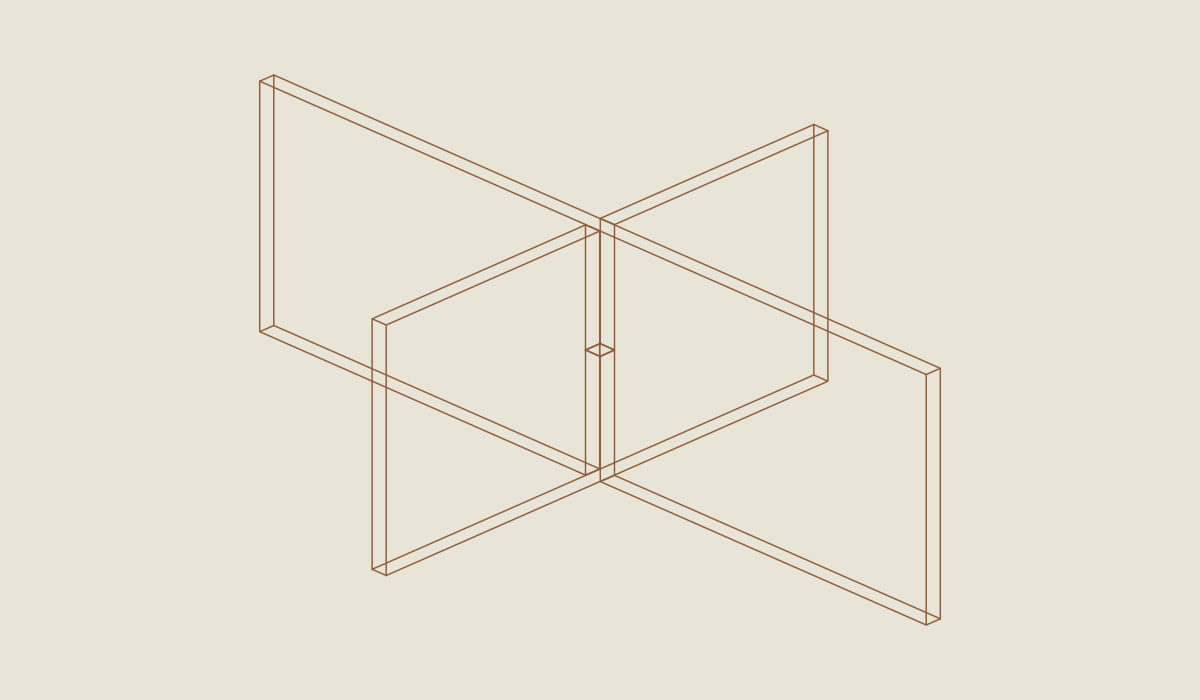
Loading the 3D view…
Drag to turn. Pinch or use + / − to zoom. The written step covers workholding and tool use.
Scroll or swipe the enlarged drawing to read its dimensions. Choose Fit to see the whole drawing again.
Check: A scrap test establishes a sliding slot fit; the final joint needs neither hammering nor a wide rocking gap.
- 11
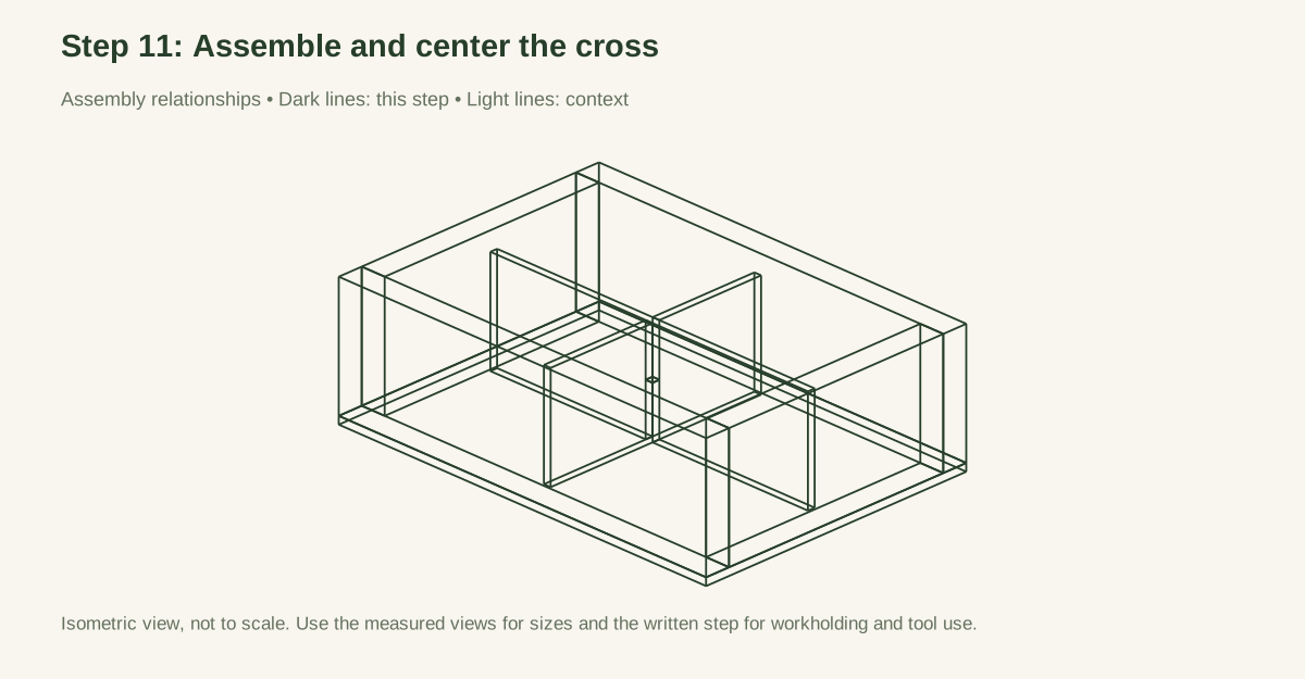
Assemble and center the cross
Bring D1 upward into D2 so the two slot bottoms meet. Their upper and lower edges should align. If one sits higher, measure slot depth rather than forcing the pieces together. Place the cross in the box with approximately 1/16 inch clearance at each end. It remains unglued and removable. No fastener passes through the floor into the divider.
Close-up · Whole model shows the complete part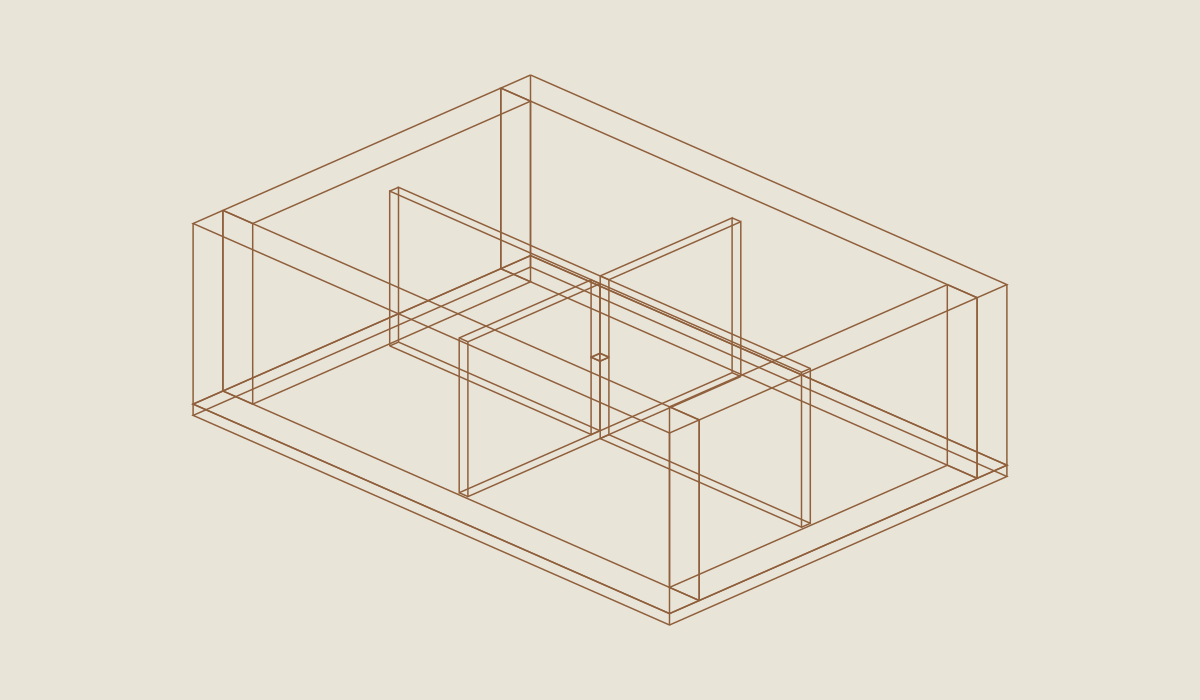
Loading the 3D view…
Drag to turn. Pinch or use + / − to zoom. The written step covers workholding and tool use.
Scroll or swipe the enlarged drawing to read its dimensions. Choose Fit to see the whole drawing again.
Check: Both divider bottoms reach the floor and the cross sits level and centered.
- 12
Label and trial the packet arrangement
Add removable category labels, then try empty or closed packets of the sizes you actually own. Make sure a hand can retrieve a packet without pulling out the whole cross. Do not pack the bays so tightly that packets bow the dividers. Note the widest packet that fits comfortably; no packet-count capacity is claimed.
Close-up · Whole model shows the complete part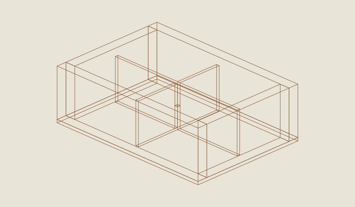
Loading the 3D view…
Drag to turn. Pinch or use + / − to zoom. The written step covers workholding and tool use.
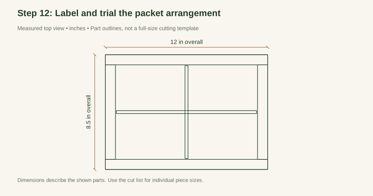
Scroll or swipe the enlarged drawing to read its dimensions. Choose Fit to see the whole drawing again.
Check: Packets lift out without bowing the dividers; this wooden organizer is not humidity-controlled seed storage.
05 / Keep it sound
Care
After the build
- Each bay is about 5.140 × 3.390 inches clear, and a packet wider than about 5 inches may not sort comfortably. Measure your widest packets first, then label the compartments and keep the dates and storage instructions on each packet.
- The removable divider should seat without force; store the sorter indoors and keep packets dry.
Check it each season
- Use the organizer when planning and sowing, then return seed to its appropriate dry, cool storage conditions. A cardboard divider label or wooden box does not control humidity. Keep packets closed and preserve their crop, variety, source, year, and any handling instructions. Do not mix unidentified loose seeds into the bays. University of Minnesota's storage guidance concerns the seed and its storage container, not a decorative open organizer.
- Keep the box away from watering, damp potting benches, and direct outdoor weather. Empty it before cleaning. Lift out the cross, brush or vacuum debris gently, and dry-clean the interior. Do not soak the plywood or spray household cleaners onto seed packets. If a bay becomes wet, remove the seed and assess it separately instead of assuming drying the box restores seed viability.
- The seed-spacing template helps transfer an appropriate sowing grid; it does not select crop spacing for you. Keep the tool caddy for tools rather than carrying open seed packets beside dirty blades.
If something looks wrong
- Divider sits high
- Check: Half-lap too shallow or cut from wrong edge. Fix: Remove and correct the joint; do not force it into the floor.
- Divider rattles
- Check: Slot too wide or end clearances excessive. Fix: Replace the loose strip; glue is not the specified repair.
- Packet catches
- Check: Veneer splinter, proud screw, overfilled bay. Fix: Empty and correct the contact point.
- Floor bows or separates
- Check: Wet storage, missed wall edge, damaged panel. Fix: Remove contents and replace damaged material.
- Seed packets feel damp
- Check: Storage conditions, nearby water. Fix: Move seed to appropriate conditions and review viability separately.
Keep exploring