Garden storage · Guide 86
Build a Passive Boot-Drying Rack
Four smooth pegs above a removable drip tray, with a broad braced base and no heater.
01 / See the shape
View the project
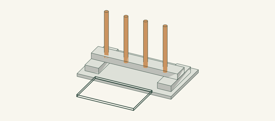
Loading the 3D view…
Drag to turn. Pinch or use + / − to zoom. The written step covers workholding and tool use.
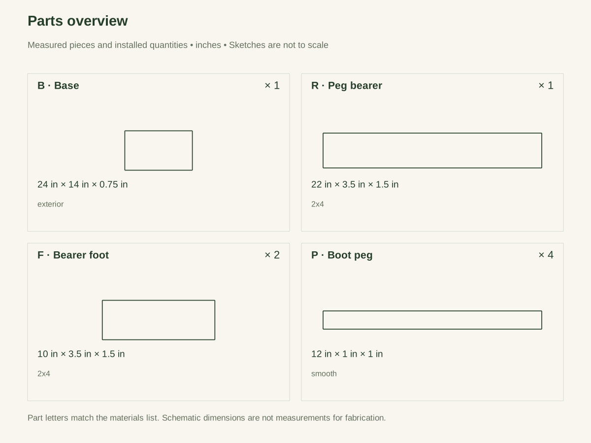
Scroll or swipe the enlarged drawing to read its dimensions. Choose Fit to see the whole drawing again.
Build a Passive Boot-Drying Rack. Check the dimensions and build steps before cutting.
02 / Plan your build
Before you start
This low rack holds two pairs of empty boots open to room air. Smooth wooden pegs support them without sharp metal hooks, and the tray can be removed for cleaning. It does not supply heat or guarantee drying time; empty and air boots according to their care instructions.
Where it goes
A level sheltered floor with room air circulation and no nearby heater, electrical lead or walking obstruction.
Footprint: 24 × 14 in frame size; allow room around it to work and for anything that projects.
What to expect
Measure accurately, make supported square cuts and drill clamped joints. Plan 3–4 hours.
A planning estimate for the hands-on work, once the materials are bought and the tools are set up. It has not been timed on a finished build.
Check the spot
- A level sheltered floor with room air circulation and no nearby heater, electrical lead or walking obstruction.
- Measure the usable stock before marking. Keep the assembly area flat and large enough to clamp the work without reaching across a moving cutter.
Stop and check first if…
- Stop if a part splits, a fixing strips, or the assembled object rocks. Unload it before opening a joint.
- Do not substitute an unknown material section or make the object taller or wider without checking every affected part and joint.
Work safely
- Clamp the rack before drilling the blind bores. Use a depth stop and account for the Forstner center tip, not only its flat cutting edge. Never hold a loose peg beside a turning blade or bit.
- Keep wet boots away from heaters and electrical leads. Lift boots off individually without levering the pegs. Empty the tray and wipe drips outside it so the rack does not create a wet walking surface.
Budget
We have not put a price on this one yet. Lumber and hardware prices change by store and season, so price the list under What you need at your local supplier before you buy.
03 / Gather and cut
What you need
B — Base
1 piece
Exterior plywood, actual 0.75 in. Buy one 24 × 24-inch exterior plywood panel, actual 0.75 in thick; cut the 24 × 14-inch base. Keep it dry during use.
Measure your boards before cutting. Build to the finished sizes written here, not the nominal lumber label.
R — Peg bearer
1 piece
Untreated surfaced 2 × 4, actual 1.5 × 3.5. Buy one 2 × 4 × 4-ft board, actual 1.5 × 3.5 in, for the 22-inch bearer and both 10-inch feet.
Measure your boards before cutting. Build to the finished sizes written here, not the nominal lumber label.
F — Bearer foot
2 pieces
Same 2 × 4 stock. Cut both feet from the board listed for R; no second board needed.
Measure your boards before cutting. Build to the finished sizes written here, not the nominal lumber label.
P — Boot peg
4 pieces
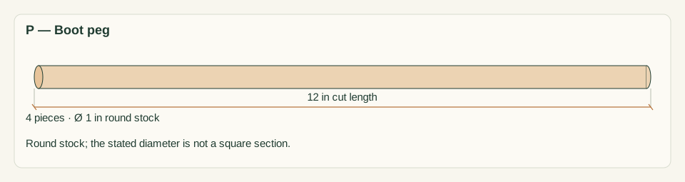
Smooth straight 1-in-diameter hardwood dowel; cut list shows its bounding section. Buy two 1-inch-diameter × 36-inch hardwood dowels; cut two 12-inch pegs from each, leaving room for kerf.
Round exposed ends smoothly; no preservative-treated or splintered dowel.
T — Drip tray
1 piece
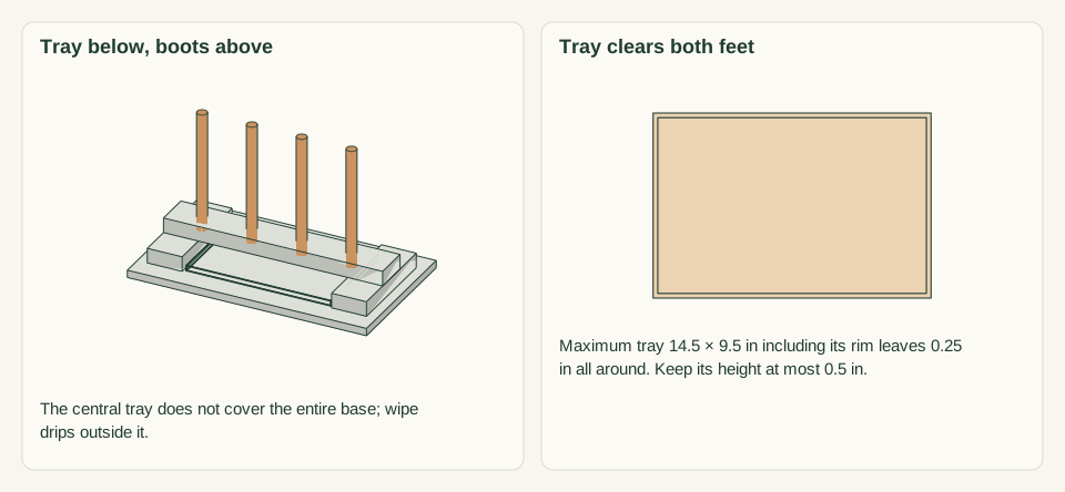
Removable washable tray no larger than 14.5 × 9.5 in outside, selected to fit between the feet. One shallow tray measured before assembly.
This central catch area does not cover the whole base; wipe any drips outside it.
Base/foot screws
8 items
#8 × 1.75-in stainless wood screws Purchase at least 8; keep spare hardware separate from the installed count.
Use one consistent product and follow its pilot and driving instructions.
Bearer screws
4 items
#8 × 2.5-in stainless wood screws Purchase at least 4; keep spare hardware separate from the installed count.
Use one consistent product and follow its pilot and driving instructions.
Peg retainers
4 items
#6 × 2-in stainless wood screws Purchase at least 4; keep spare hardware separate from the installed count.
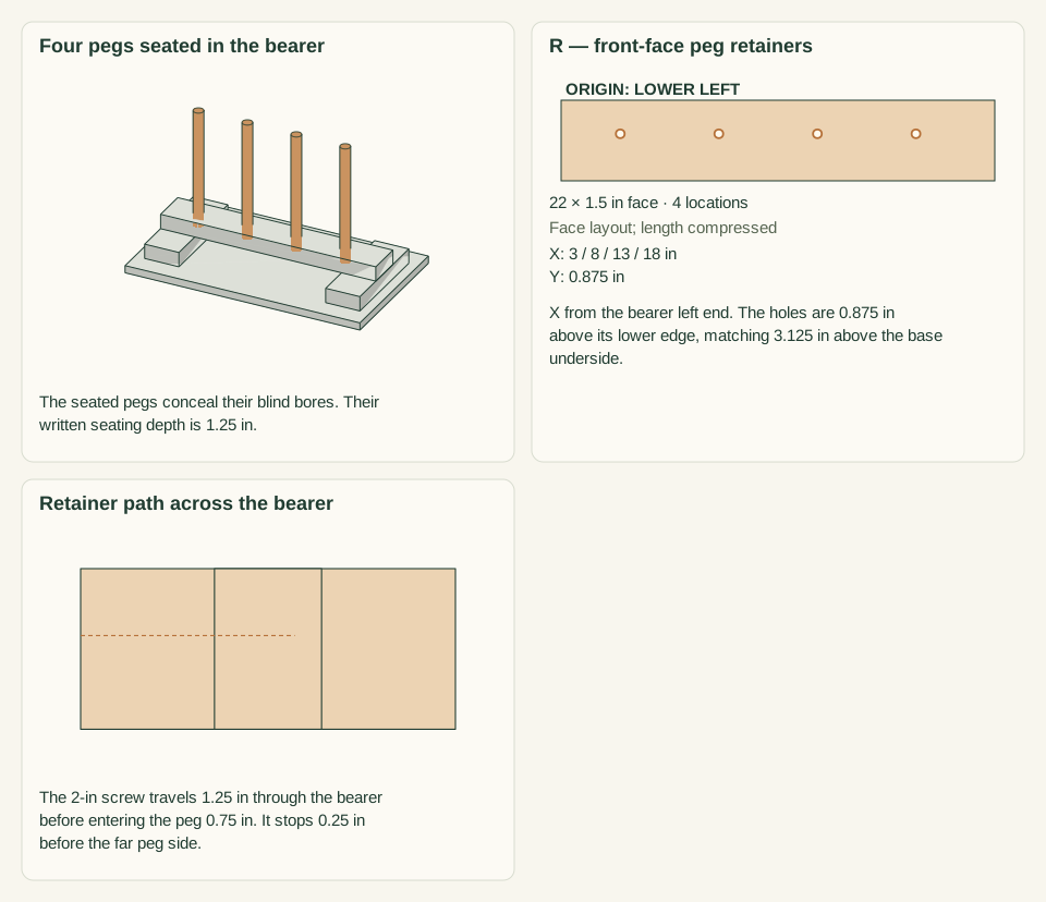
Drive horizontally from the FRONT bearer face, centered on each peg at 3.125 in above the base underside; 0.75-in nominal bite into the dowel.
Adhesive
1 item
Exterior wood adhesive compatible with dowel and bearer Buy one small bottle of exterior wood adhesive compatible with the actual hardwood and bearer.
Apply only inside the peg joints as the label directs, wipe squeeze-out and allow the stated full cure.
Cut list
| Piece | How many | Cut length | Note |
|---|---|---|---|
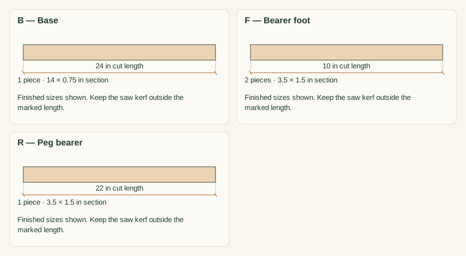
| B — Base | 1 | 24 × 14 × 0.75 in | Finished length × width × thickness; square ends unless the detail says otherwise. |
| R — Peg bearer | 1 | 22 × 3.5 × 1.5 in | Finished length × width × thickness; square ends unless the detail says otherwise. |
| F — Bearer foot | 2 | 10 × 3.5 × 1.5 in | Finished length × width × thickness; square ends unless the detail says otherwise. |
| P — Boot peg | 4 | 12 × 1 × 1 in | Finished length × width × thickness; square ends unless the detail says otherwise. |
Tools
- Tape or rule, square and sharp pencil
- Clamps, a flat bench and sacrificial backing
- Suitable guarded saw for the specified stock
- Drill/driver, depth stop and bits matched to the chosen screws
- Fine abrasive and a dust brush
- 1-inch Forstner bit with depth stop and center tip no longer than 1/8 inch; a drill guide for vertical bores; adhesive brush or applicator
Protective gear
- Eye protection during cutting and drilling
- Hearing protection and dust collection appropriate to the actual tools
- Closed footwear; keep loose clothing and gloves away from rotating cutters
04 / Put it together
Build steps
- 01
Check footwear fit
Place the largest empty boots around four mock pegs on 5-inch centers. Check that uppers do not press tightly against each other and that the rack fits the intended floor without a trip projection.
Close-up · Whole model shows the complete part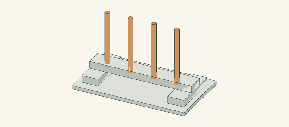
Loading the 3D view…
Drag to turn. Pinch or use + / − to zoom. The written step covers workholding and tool use.
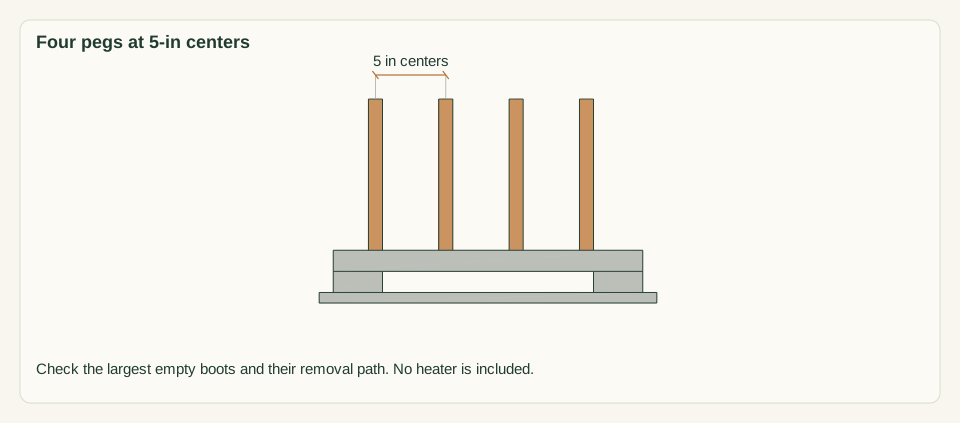
Scroll or swipe the enlarged drawing to read its dimensions. Choose Fit to see the whole drawing again.
Trial the actual empty boots at the four peg positions before building. The complete rack is a space reference, not a footwear fit guarantee.
Check: Two pairs fit loosely with an unobstructed removal path.
- 02
Cut the base and wood supports
Cut the 24 × 14 base, two 10-inch feet and one 22-inch bearer. Record the actual 1.5-inch stock thickness and check the plywood for delamination. Smooth all exposed foot and base corners.
Close-up · Whole model shows the complete part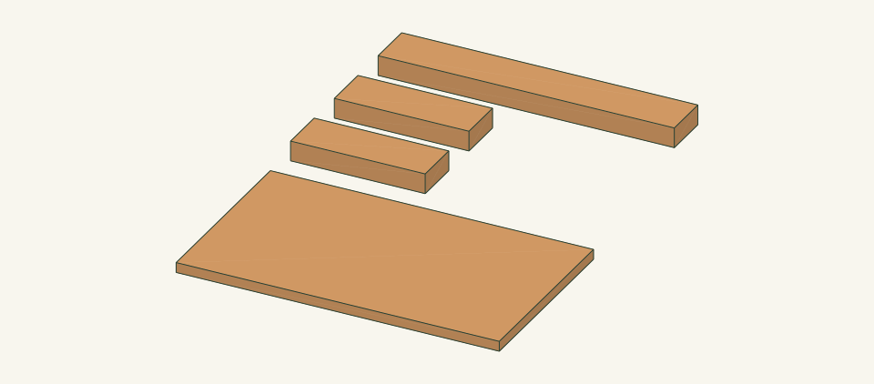
Loading the 3D view…
Drag to turn. Pinch or use + / − to zoom. The written step covers workholding and tool use.
Scroll or swipe the enlarged drawing to read its dimensions. Choose Fit to see the whole drawing again.
Cut the base, two feet and cross bearer before drilling or adding dowels.
Check: Supports lie flat and match the drawing’s actual sections.
- 03
Locate and fasten both feet
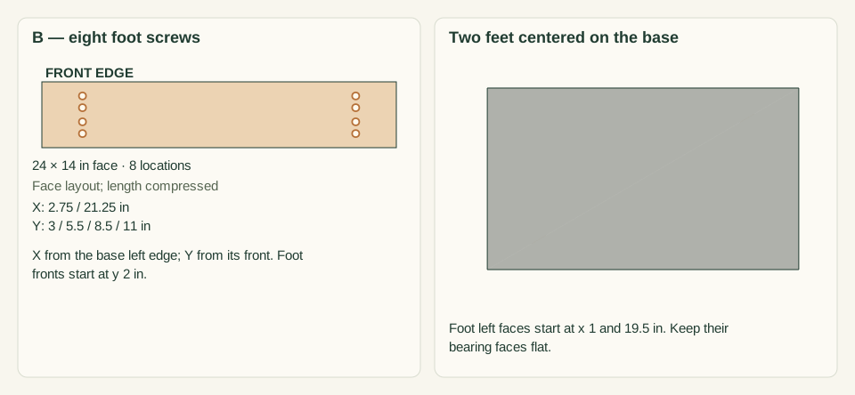
Place the left foot with its left edge 1 inch from the base left edge and the right foot at 19.5 inches. Both front ends are 2 inches from the base front. Mark underside screw columns x=2.75 and 21.25; on each column mark y=3, 5.5, 8.5 and 11 inches from the base front. Clamp, drill clearances through the base and pilots into feet, then fit eight #8 × 1.75-inch screws.
Close-up · Whole model shows the complete part
Loading the 3D view…
Drag to turn. Pinch or use + / − to zoom. The written step covers workholding and tool use.
Scroll or swipe the enlarged drawing to read its dimensions. Choose Fit to see the whole drawing again.
Fasten through the base underside into the centers of both feet. The cross bearer is a later step.
Check: Both 10-inch feet are centered front-to-back and all eight underside heads are flush.
- 04
Position the cross bearer
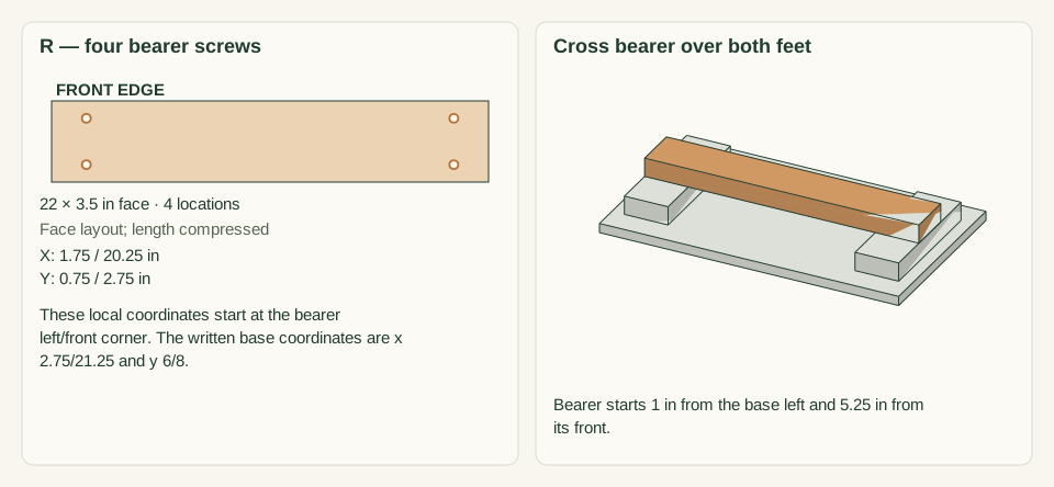
Place the bearer with its left end 1 inch from the base left edge and its front edge 5.25 inches from the base front. It spans both feet. Mark four top screws: x=2.75 and 21.25, each at y=6 and 8, all measured from the base front-left. Drill clearances through the bearer and pilots into feet; fit four #8 × 2.5-inch screws.
Close-up · Whole model shows the complete part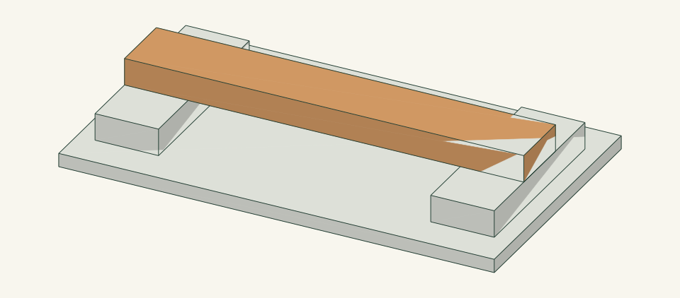
Loading the 3D view…
Drag to turn. Pinch or use + / − to zoom. The written step covers workholding and tool use.
Scroll or swipe the enlarged drawing to read its dimensions. Choose Fit to see the whole drawing again.
Place the bearer across the two feet, then fasten down through it without entering future peg locations.
Check: The bearer is level and the four screws stay clear of the peg centers and base screws.
- 05
Mark the four peg centers
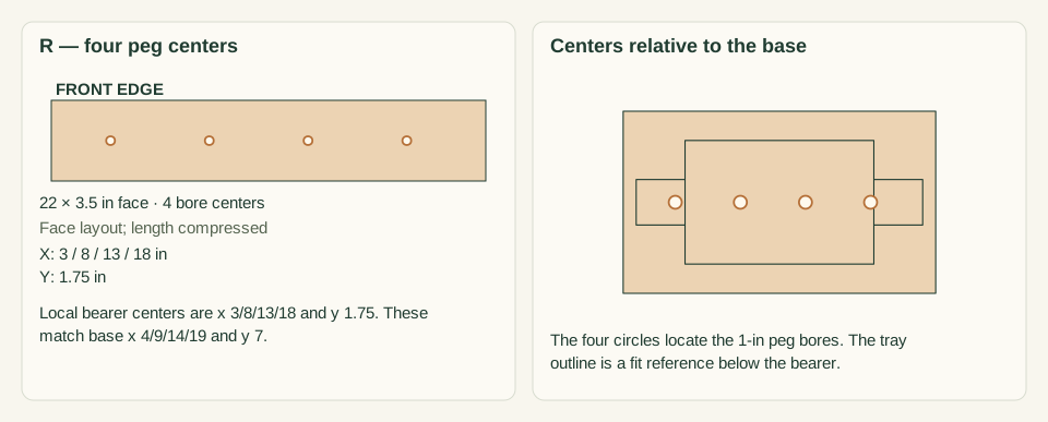
On the bearer top mark x 4, 9, 14, 19 inches from the base left starting edge and y 7 from the front. Check each point against screw locations underneath before drilling.
Close-up · Whole model shows the complete part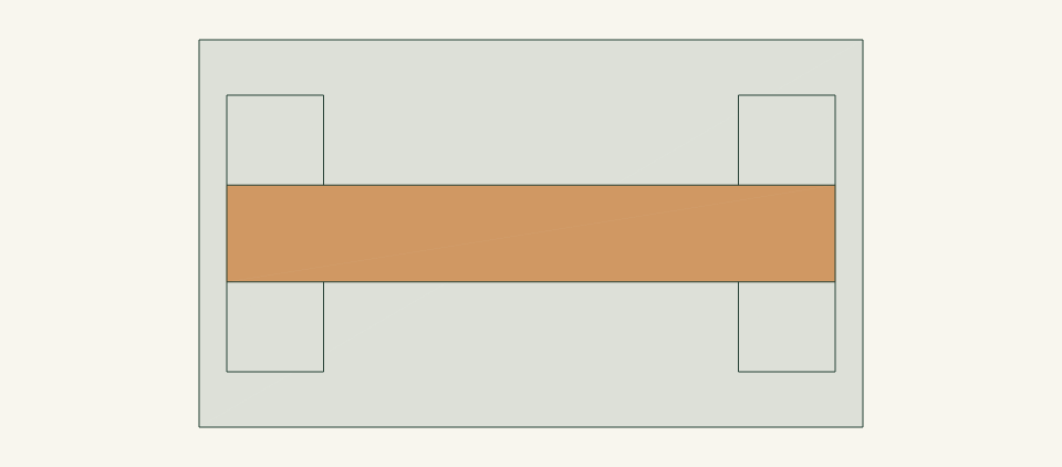
Loading the 3D view…
Drag to turn. Pinch or use + / − to zoom. The written step covers workholding and tool use.
Scroll or swipe the enlarged drawing to read its dimensions. Choose Fit to see the whole drawing again.
Mark the four peg centers on the bearer top after the support frame is assembled.
Check: Four centers are 5 inches apart and do not hit existing hardware.
- 06
Drill four controlled blind bores
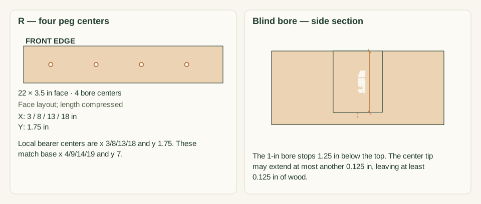
Clamp the rack securely on a supported surface. Use a 1-inch Forstner bit with a depth stop and a center tip no longer than 1/8 inch beyond its flat cutting edge. Test the actual dowel in scrap first. Drill the FLAT bottom of each bore 1.25 inches below the bearer top; its center tip may go no deeper than 1.375 inches. Clear chips only with the drill stopped.
Close-up · Whole model shows the complete part
Loading the 3D view…
Drag to turn. Pinch or use + / − to zoom. The written step covers workholding and tool use.
Scroll or swipe the enlarged drawing to read its dimensions. Choose Fit to see the whole drawing again.
Drill controlled blind bores in the supported bearer. The depth section is essential: these must not become through holes.
Check: At least 0.125 inch of wood remains even beneath the center tip; no bore breaks through.
- 07
Cut and ease the pegs
Cut four 12-inch dowel lengths with supported work, allowing kerf. Round exposed ends gently and sand the full boot-contact surface. Do not reduce the insertion diameter so much that it rattles.
Close-up · Whole model shows the complete part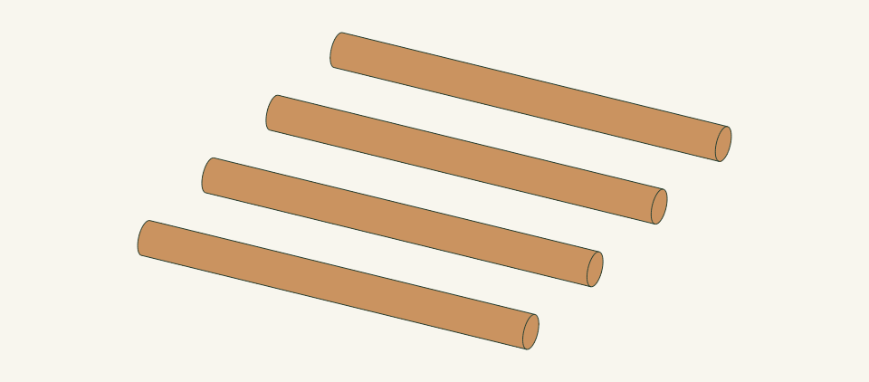
Loading the 3D view…
Drag to turn. Pinch or use + / − to zoom. The written step covers workholding and tool use.
Scroll or swipe the enlarged drawing to read its dimensions. Choose Fit to see the whole drawing again.
Cut four loose round dowels, then ease their ends by hand. Their cylindrical shape is preserved in the 3D layout.
Check: All four pegs are smooth, straight and fit their numbered bores.
- 08
Glue and mechanically retain the pegs
Glue and seat each 12-inch peg 1.25 inches into its numbered bore. On the FRONT vertical bearer face mark the four peg centerlines x=4, 9, 14 and 19 from the base left edge, at height 3.125 inches above the BASE underside. Clamp and drill a product-matched pilot horizontally into each peg. Fit four #6 × 2-inch screws: 1.25 inches through the bearer before 0.75 inch enters the dowel. Allow full adhesive cure.
Close-up · Whole model shows the complete part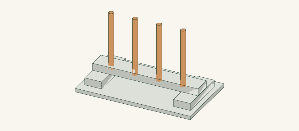
Loading the 3D view…
Drag to turn. Pinch or use + / − to zoom. The written step covers workholding and tool use.
Scroll or swipe the enlarged drawing to read its dimensions. Choose Fit to see the whole drawing again.
Seat each glued peg in its numbered bore and retain it horizontally from the bearer front. No screw point may emerge from the far peg surface.
Check: Screws stop 0.25 inch before the far side of each dowel and no sharp point touches a boot.
- 09
Fit drainage and try empty boots
Slide the selected shallow tray from the FRONT into the 15-inch gap between the feet. Its whole rim must fit within 14.5 × 9.5 inches and be at most 0.5 inch high, leaving room under the bearer. Center it 0.25 inch from each foot. Try empty boots separately, stop for movement, and wipe drips outside the central tray.
Close-up · Whole model shows the complete part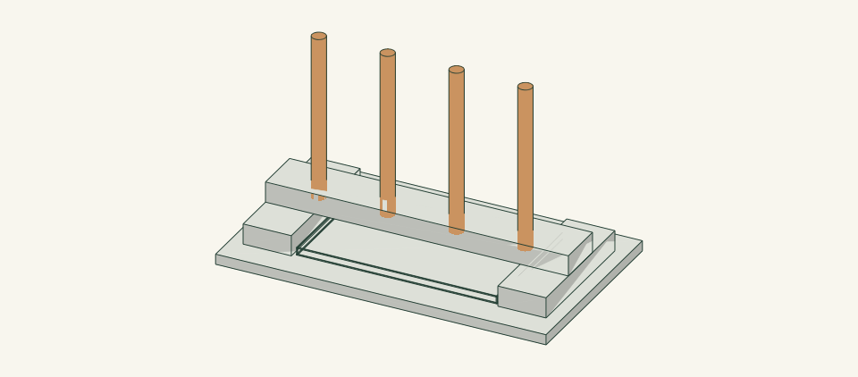
Loading the 3D view…
Drag to turn. Pinch or use + / − to zoom. The written step covers workholding and tool use.
Scroll or swipe the enlarged drawing to read its dimensions. Choose Fit to see the whole drawing again.
Slide the actual catch tray through the front beneath the bearer; try empty boots individually after the adhesive cures.
Check: Boots are supported without crowding and the tray remains removable.
- 10
Dry passively and keep clean
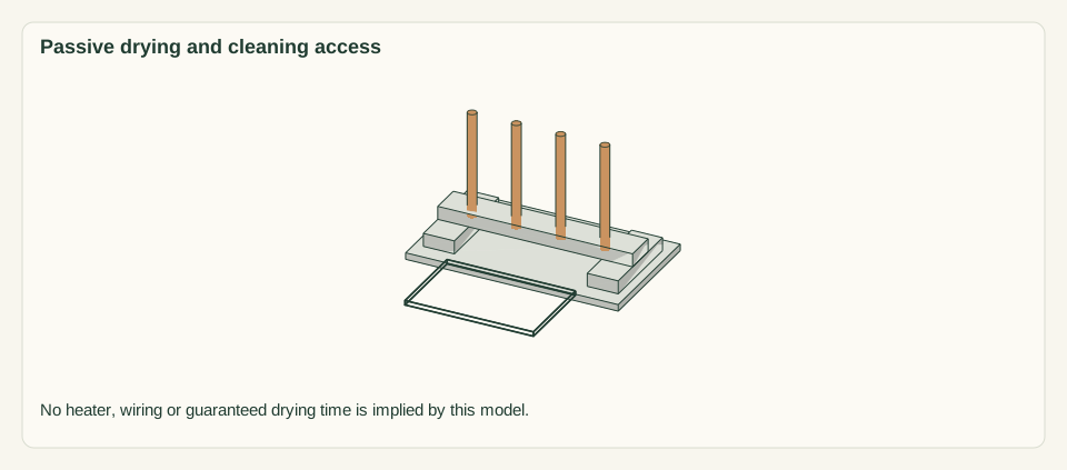
Follow the footwear care guidance for room-air drying. Do not place the rack on a heater or fit heating elements. Empty the tray, wipe the pegs and let the whole rack dry between uses.
Close-up · Whole model shows the complete partLoading the 3D view…
Drag to turn. Pinch or use + / − to zoom. The written step covers workholding and tool use.
Scroll or swipe the enlarged drawing to read its dimensions. Choose Fit to see the whole drawing again.
Remove boots, slide out the tray and dry the parts with room air. The shifted outline is the front cleaning route.
Check: No standing water, electrical addition or cracked peg remains in service.


05 / Keep it sound
Care
After the build
- Do not force narrow boots over a peg. Change the storage method when shaft width or boot mass makes removal unstable.
- No person may stand, sit or climb on this low rack; pegs are not handrails.
Check it each season
- Inspect connections and hand-contact edges before use. Unload before tightening or replacing parts; replace a cracked member rather than adding a screw beside the crack.
- Brush off debris, wipe only as needed and dry with air around the joints. Store dry when the item is not in use.
If something looks wrong
- Peg loosens
- Remove the boots, inspect bore/retainer damage and replace the affected parts before reuse.
- A boot traps on a peg
- Support the boot and lift straight up; do not lever the whole rack by the upper.
- Drying is slow
- Separate boots and improve safe room airflow according to their care instructions; do not improvise a heater.
- Base or tray stays wet
- Empty the tray and dry all interfaces; replace damaged panel material.
Keep exploring