Garden benches · Guide 44
Build a Long Garden Bench With a Fitted Center Support
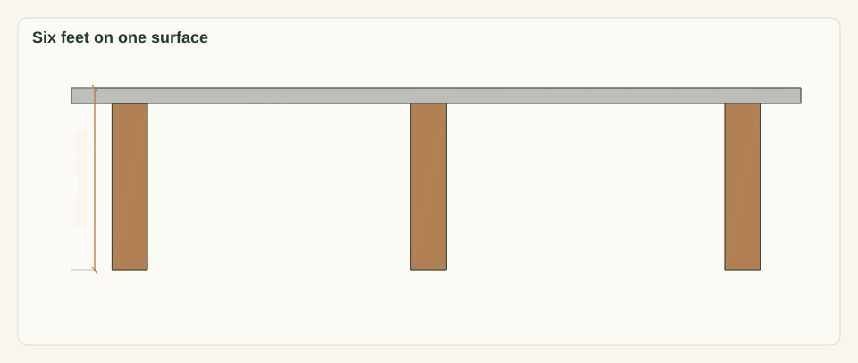
Build a 72-inch backless cedar bench with a third leg station at mid-length. The center legs are fitted on the finished paved surface so all six legs bear under the seat.
01 / See the shape
View the project
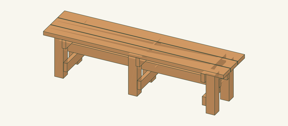
Loading the 3D view…
Drag to turn. Pinch or use + / − to zoom. The written step covers workholding and tool use.

Scroll or swipe the enlarged drawing to read its dimensions. Choose Fit to see the whole drawing again.
Every joint, screw head and slat end is checked before the first sitting test.
02 / Plan your build
Before you start
A 72-inch seat on two end stations would leave the slats spanning 54 inches between bearing blocks. A center station cuts that to two 24.5-inch spans, but only when its legs actually bear. This design builds the two end frames on the bench, then stands them on the final surface. Continuous rails R tie them together. The two center legs are clamped to the rails one at a time with their feet pressed onto the same surface, and only then are they screwed. The bench fails if the center feet hang clear of the surface, because the slats then bend over the full 54-inch span. It also fails if the bench rocks on a surface that is not flat, or if it is moved to a new surface without refitting the center legs.
Where it goes
A firm, flat paved or paver surface at least 72 × 17 in plus working access, with no gap over 0.0625 in under a straightedge along each leg line. Do not place it on lawn, bare soil, a slope or a deck of unknown capacity.
Footprint: 72 × 17 in seat over a 64 × 15 in leg footprint. Allow 30 in clear on each long side and 24 in at each end for building and use, about 132 × 77 in in all
What to expect
Measure accurately, crosscut 4 × 4 stock square and drive piloted screws in clamped joints. Plan 6–8 hours of work for two people, plus finish drying time on the product label.
A planning estimate for the hands-on work, once the materials are bought and the tools are set up. It has not been timed on a finished build.
Check the spot
- A firm paved or paver surface at least 72 × 17 in, with no gap over 0.0625 in under a straightedge along each 64 in leg line or across each 15 in station.
- Clear access of 30 in on each long side and 24 in at each end, with no step, edge or drop within reach of the seat.
- A flat bench or floor for assembling the end frames, and room to support 8 ft boards on both sides of the saw.
Stop and check first if…
- Stop if the site straightedge shows a gap over 0.0625 in. Regrade or choose another surface; do not compensate by trimming one leg.
- Stop if a center foot will not touch the surface while its top is in line with the end cleats. The surface is not flat enough for this design.
- Stop if a part splits, a screw strips, or the stock section differs from the parts table. Rework the cut lengths or replace the part before continuing.
Work safely
- Support 4 × 4 stock on both sides of the cut and clamp it. Never hold a 16.5 in leg offcut by hand beside the blade.
- Clamp each part to backing before drilling, and keep the drill handle braced against reaction torque when driving 3 in screws.
- Follow the saw, drill and finish manufacturer instructions. Keep guards in place and disconnect power before changing a blade or bit.
- Lift and tip the assembled frame with two people by the rails. Oily finishing rags can self-heat: dry them flat outdoors or seal them in a water-filled metal can.
Budget
We have not put a price on this one yet. Lumber and hardware prices change by store and season, so price the list under What you need at your local supplier before you buy.
03 / Gather and cut
What you need
L — Leg
6 pieces
Western red cedar or redwood 4 × 4; actual 3.5 × 3.5 in. Two 4 × 4 × 8 ft boards. Per board: 3 × 16.5 + 3 kerfs × 0.125 + 1 in end trim = 50.875 in of 96 in.
All six legs must match within 0.0625 in. The center legs carry seat load only if they are the same length as the end legs.
C — Station cleat
3 pieces
Western red cedar or redwood 2 × 4; actual 1.5 × 3.5 in. Cut one C from each of the three 2 × 4 × 8 ft boards listed under R and T.
C length equals the 17 in seat depth. Mark the front end and the inboard face on each piece.
T — Station tie
3 pieces
Western red cedar or redwood 2 × 4; actual 1.5 × 3.5 in. All three from 2 × 4 board 3: C 17 + 3 × T 15 + 4 kerfs × 0.125 + 1 in trim = 63.5 in of 96 in.
T length equals the 15 in outside width across a pair of legs. Mark the front end on each piece.
R — Long rail
2 pieces
Western red cedar or redwood 2 × 4; actual 1.5 × 3.5 in. Two 2 × 4 × 8 ft boards (boards 1 and 2). Each: R 64 + C 17 + 2 kerfs × 0.125 + 1 in trim = 82.25 in of 96 in.
Choose the two straightest 2 × 4 boards for R. Reject bow over 0.125 in along the 64 in length.
S — Seat slat
3 pieces
Western red cedar or redwood 2 × 6; actual 1.5 × 5.5 in. Three 2 × 6 × 8 ft boards. Each: 72 + 1 kerf × 0.125 + 1 in trim = 73.125 in of 96 in.
Choose the best face as the seat face. Reject cupping that lifts an edge more than 0.0625 in off a flat surface.
Frame and seat screws
54 items
#10 × 3 in Type 316 stainless steel wood screws, for exterior use with cedar or redwood Buy one pack of at least 54 plus spares for a test joint in offcut; keep spares separate from the installed count.
12 in C, 12 in T, 12 in R, 18 in S. Each passes through 1.5 in and engages 1.5 in of the receiving part. Follow the product's clearance and pilot sizes. No connection capacity is inferred.
Cut list
| Piece | How many | Cut length | Note |
|---|---|---|---|
| L — Leg | 6 | 16.5 × 3.5 × 3.5 in | Square both ends; ease the bottom edges 0.125 in without shortening the leg. |
| C — Station cleat | 3 | 17 × 3.5 × 1.5 in | Finished length × width × thickness; square ends unless the detail says otherwise. |
| T — Station tie | 3 | 15 × 3.5 × 1.5 in | Finished length × width × thickness; square ends unless the detail says otherwise. |
| R — Long rail | 2 | 64 × 3.5 × 1.5 in | Finished length × width × thickness; square ends unless the detail says otherwise. |
| S — Seat slat | 3 | 72 × 5.5 × 1.5 in | Finished length × width × thickness; square ends unless the detail says otherwise. |
Tools
- Tape measure, combination square, sharp pencil and a 72 in or longer straightedge
- Level of at least 24 in
- Guarded saw able to crosscut 3.5 in square stock in one controlled pass, or in two matched passes
- Drill/driver with clearance bits, pilot bits and a countersink matched to the chosen screws
- At least four bar clamps with 24 in capacity
- 0.25 in spacers, sanding block, 120-grit abrasive and a block plane
Protective gear
- Eye protection during cutting, drilling and driving
- Hearing protection and dust control suited to the actual saw
- Closed footwear and work gloves for handling stock, removed near rotating cutters
- Chemical-resistant gloves if applying finish
04 / Put it together
Build steps
- 01
Confirm the site and intended use
Choose a firm paved or paver surface at least 72 × 17 in, with 30 in clear on each long side and 24 in at each end. Lay a straightedge along the front and back leg lines, each 64 in long and 15 in apart. Lay it across each of the three stations at 6.5, 36 and 65.5 in from the left seat end. Check level in both directions.
Close-up · Whole model shows the complete part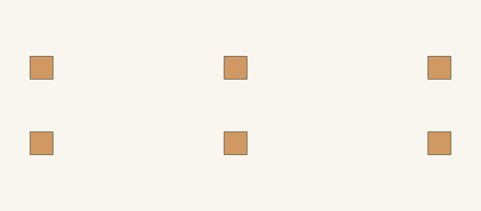
Loading the 3D view…
Drag to turn. Pinch or use + / − to zoom. The written step covers workholding and tool use.
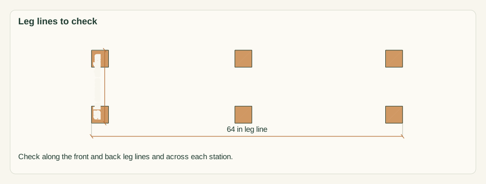
Scroll or swipe the enlarged drawing to read its dimensions. Choose Fit to see the whole drawing again.
Planning reference only: the six leg positions show where the straightedge must lie flat.
Check: No gap under the straightedge exceeds 0.0625 in anywhere, and the surface does not flex or sound hollow underfoot.
- 02
Inspect and measure the stock
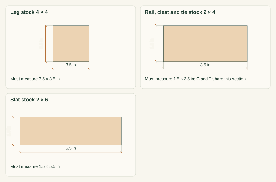
Measure every board at both ends and the middle. The 4 × 4 boards for L must be 3.5 × 3.5 in, the 2 × 4 boards for R, C and T 1.5 × 3.5 in, and the 2 × 6 boards for S 1.5 × 5.5 in. Reject splits within 6 in of an end, loose knots, twist, or bow over 0.125 in. Set aside the two straightest 2 × 4 boards for R.
Close-up · Whole model shows the complete part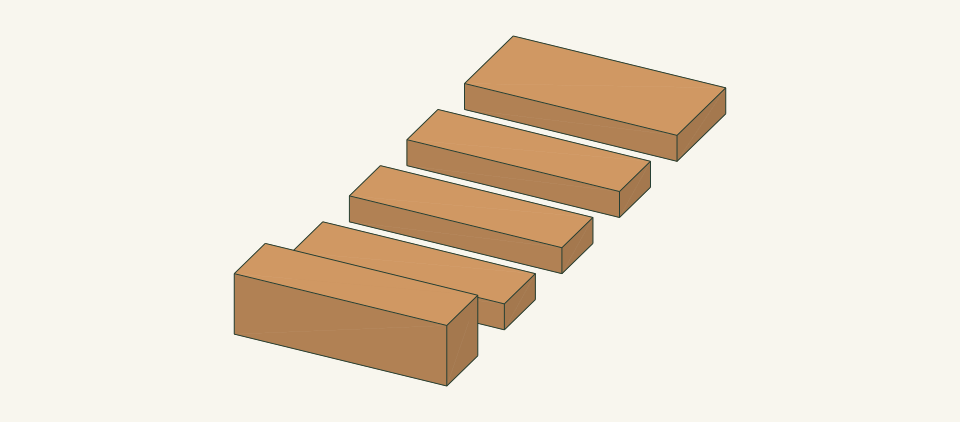
Loading the 3D view…
Drag to turn. Pinch or use + / − to zoom. The written step covers workholding and tool use.
Scroll or swipe the enlarged drawing to read its dimensions. Choose Fit to see the whole drawing again.
Compare each board end against the actual sections before any cut.
Check: Every section matches the parts table, or work stops until the cut lengths are reworked for the stock in hand.
- 03
Cut the six legs
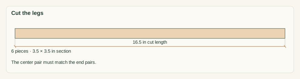
Square one end of each 4 × 4 board. Cut three legs L at 16.5 in from each board. Stand all six L on end on a flat surface and lay a straightedge across their tops. Ease the bottom edges 0.125 in with a block plane or sanding block, without shortening any leg.
Close-up · Whole model shows the complete part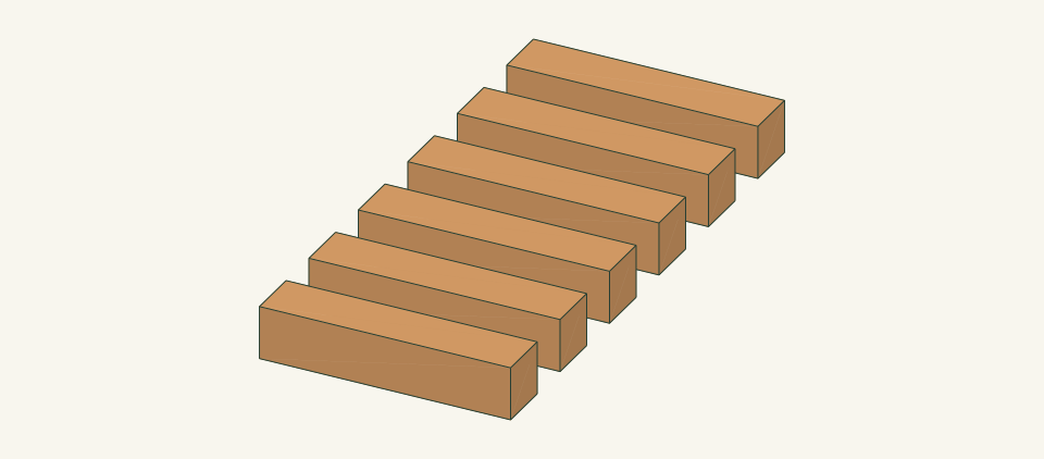
Loading the 3D view…
Drag to turn. Pinch or use + / − to zoom. The written step covers workholding and tool use.
Scroll or swipe the enlarged drawing to read its dimensions. Choose Fit to see the whole drawing again.
Six identical legs, three from each 4 × 4 board.
Check: All six L match within 0.0625 in and every cut end is square to two adjacent faces.
- 04
Cut the rails, cleats and ties
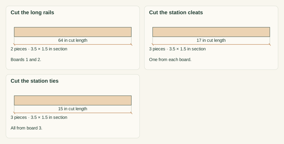
Square one end of each 2 × 4 board. From boards 1 and 2, cut one R at 64 in and one C at 17 in each. From board 3, cut one C at 17 in and three T at 15 in. Label every piece and mark the front end of each C and T.
Close-up · Whole model shows the complete part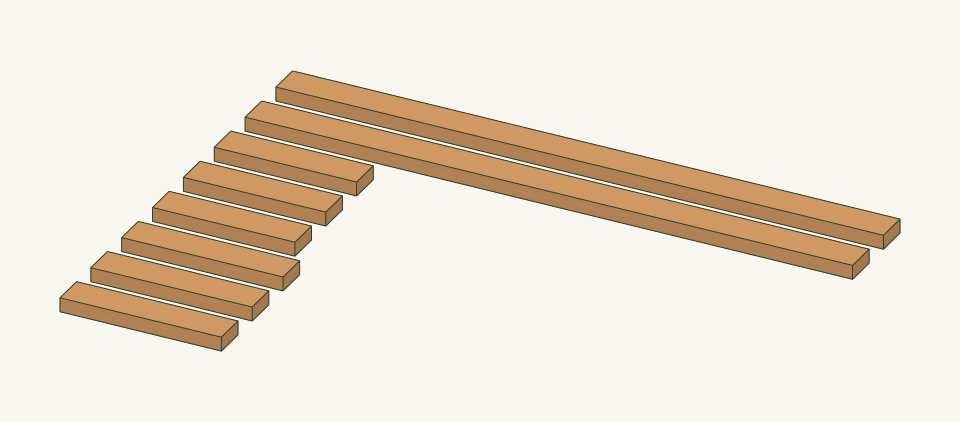
Loading the 3D view…
Drag to turn. Pinch or use + / − to zoom. The written step covers workholding and tool use.
Scroll or swipe the enlarged drawing to read its dimensions. Choose Fit to see the whole drawing again.
All 2 × 4 parts come from three boards; label each and mark its front end.
Check: Two R match within 0.0625 in, three C at 17 in and three T at 15 in match within 0.0625 in.
- 05
Cut the seat slats
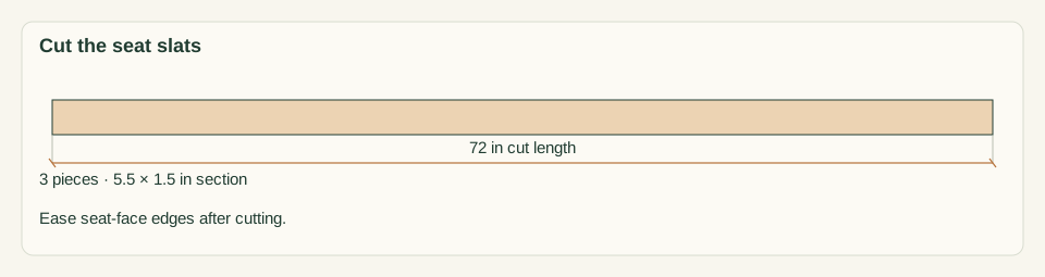
Square one end of each 2 × 6 board and cut one slat S at 72 in from each. Mark the seat face, the left end and the front edge on each S. Ease the seat-face edges and both cut ends with a 0.125 in round-over or a sanding block.
Close-up · Whole model shows the complete part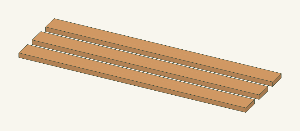
Loading the 3D view…
Drag to turn. Pinch or use + / − to zoom. The written step covers workholding and tool use.
Scroll or swipe the enlarged drawing to read its dimensions. Choose Fit to see the whole drawing again.
One slat from each 2 × 6 board, with the seat face, left end and front edge marked.
Check: Three S lie face to face with ends within 0.0625 in and no splinters on the seat face.
- 06
Mark and drill the cleats and ties
Lay each C inboard face up. Measure from the front end and the bottom edge, then mark points at 2.75 and 14.25 in along, each at 1 and 2.5 in up. On each T, mark points at 1.75 and 13.25 in along, each at 1 and 2.5 in up. Drill a clearance hole for the selected screw through each point, 24 holes in all, with the piece clamped to backing.
Close-up · Whole model shows the complete part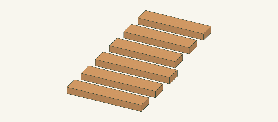
Loading the 3D view…
Drag to turn. Pinch or use + / − to zoom. The written step covers workholding and tool use.
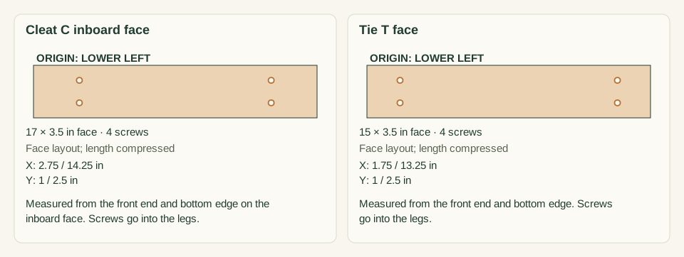
Scroll or swipe the enlarged drawing to read its dimensions. Choose Fit to see the whole drawing again.
The cleat and tie holes line up with the centers of the leg faces they screw into.
Check: Count 12 holes in the three C and 12 in the three T, all square to the face and none within 0.75 in of an edge.
- 07
Assemble the two end frames
Lay L0 and L1 on a flat bench, 8 in apart between inner faces. Clamp C0 across them with its top edge flush with the leg tops and its ends 1 in past each leg outer face. Clamp T0 with its bottom edge 3 in above the leg bottoms and its ends flush with the leg outer faces. Pilot into the legs through the holes and drive 8 screws. Build L4, L5, C2 and T2 the same way.
Close-up · Whole model shows the complete part
Loading the 3D view…
Drag to turn. Pinch or use + / − to zoom. The written step covers workholding and tool use.
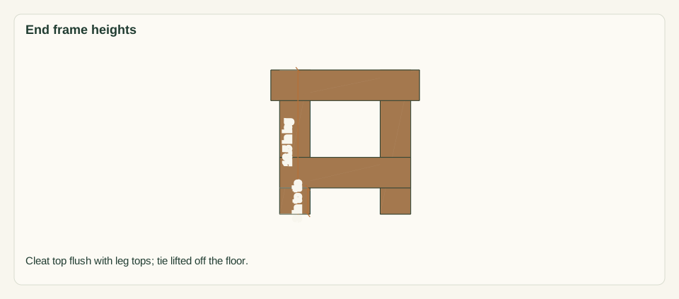
Scroll or swipe the enlarged drawing to read its dimensions. Choose Fit to see the whole drawing again.
The two end frames are identical; the cleats end up facing each other.
Check: Each frame is 15 in wide across the legs, and the diagonals across the outer leg corners both read 22.3 in within 0.0625 in.
- 08
Mark and drill the long rails
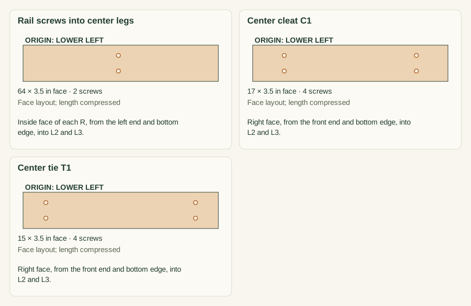
Lay both R inside face up and mark the left end. Measure from the left end and the bottom edge. Mark points at 1.75, 31.25 and 62.25 in along, each at 1 and 2.5 in up. Drill a clearance hole through each point, 12 holes in all, with the rail clamped to backing.
Close-up · Whole model shows the complete part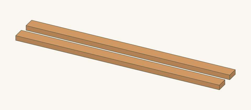
Loading the 3D view…
Drag to turn. Pinch or use + / − to zoom. The written step covers workholding and tool use.
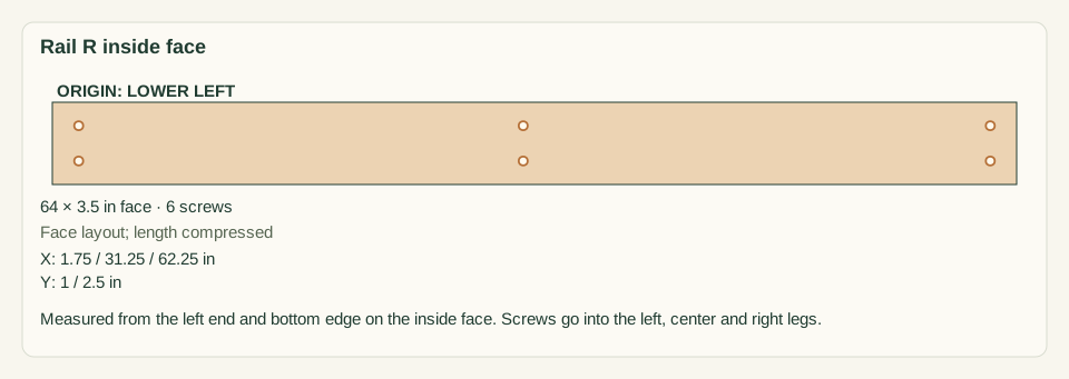
Scroll or swipe the enlarged drawing to read its dimensions. Choose Fit to see the whole drawing again.
Both rails share one hole pattern measured from the end at the left station.
Check: Both R show six holes in matching positions, and the 31.25 in pair lies 29.5 to 33 in from the left end.
- 09
Join the end frames with the rails on site
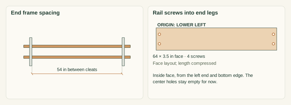
Stand both end frames on the checked surface with C0 and C2 facing each other, 54 in apart between cleat faces. Clamp R0 to the inside faces of L0 and L4 and R1 to L1 and L5. Push each R up tight under the cleats, so its bottom edge is 9.5 in above the surface. Set the R ends flush with the leg outer faces. Pilot and drive 2 screws into each end leg, 8 in all.
Close-up · Whole model shows the complete part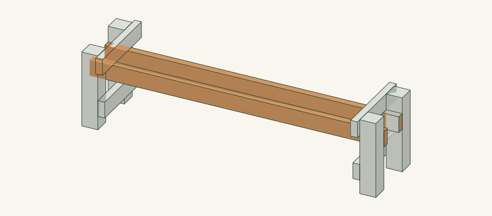
Loading the 3D view…
Drag to turn. Pinch or use + / − to zoom. The written step covers workholding and tool use.
Scroll or swipe the enlarged drawing to read its dimensions. Choose Fit to see the whole drawing again.
Rails run tight under the cleats and tie the end frames on the final surface.
Check: Leg outer faces are 64 in apart at front and back, and the plan diagonals across the leg corners match at 65.73 in within 0.125 in.
- 10
Fit the center legs to the surface
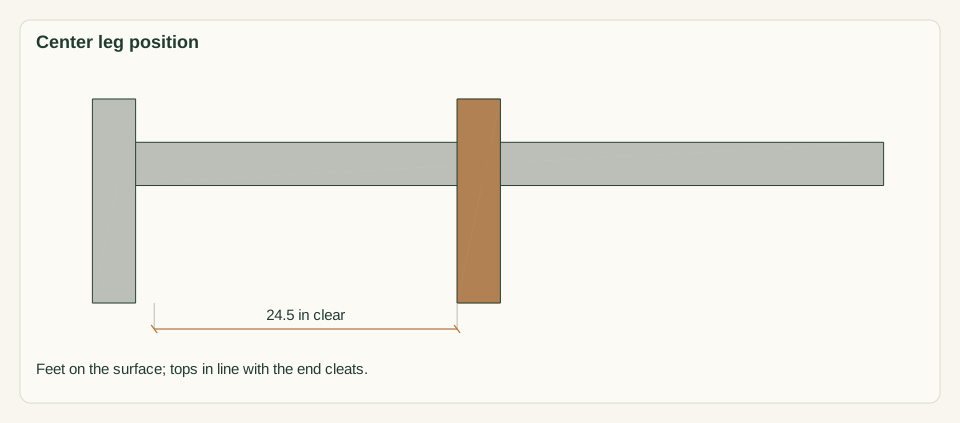
Stand L2 outside R0 with its left face 29.5 in from the R0 left end, which is 33.5 in from the seat datum. Press the foot onto the surface, plumb the leg both ways, and clamp it to R0. Fit L3 to R1 the same way. Lay a straightedge from the top of C0 to the top of C2 across both center legs.
Close-up · Whole model shows the complete part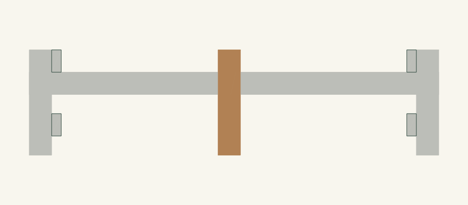
Loading the 3D view…
Drag to turn. Pinch or use + / − to zoom. The written step covers workholding and tool use.
Scroll or swipe the enlarged drawing to read its dimensions. Choose Fit to see the whole drawing again.
Each center leg is clamped alone so its own foot finds the surface.
Check: Both center feet sit on the surface with no daylight, and both leg tops touch the straightedge within 0.0625 in.
- 11
Fasten the center station
Keep the clamps on and press down on R above each center leg. Pilot and drive 2 screws through each R into L2 and L3 at 31.25 in, 4 in all. Clamp C1 to the right faces of L2 and L3, top flush with the leg tops and ends 1 in past the leg outer faces, then drive 4 screws. Clamp T1 with its bottom 3 in above the surface and its ends flush, then drive 4 screws.
Close-up · Whole model shows the complete part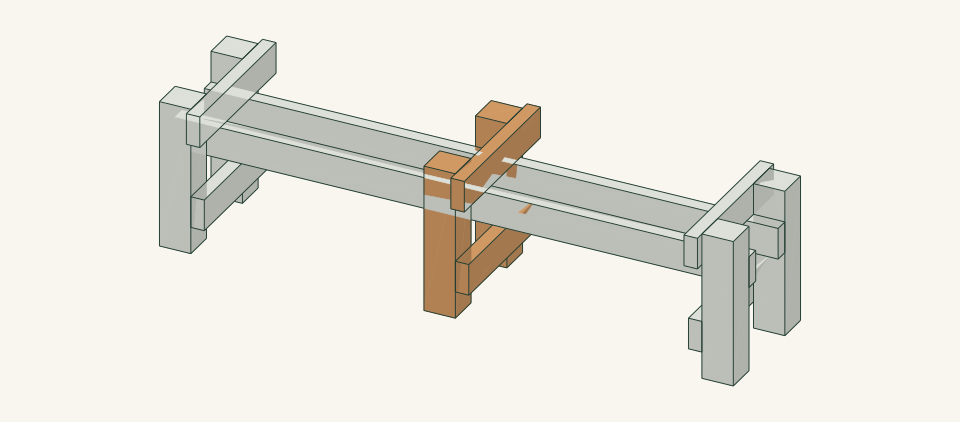
Loading the 3D view…
Drag to turn. Pinch or use + / − to zoom. The written step covers workholding and tool use.
Scroll or swipe the enlarged drawing to read its dimensions. Choose Fit to see the whole drawing again.
Screw the rails into the center legs first, then add the cleat and tie.
Check: All 12 center screws are seated, and a straightedge from C0 to C2 still touches C1 within 0.0625 in.
- 12
Sand and finish the frame and slats
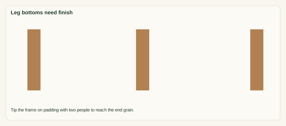
Sand exposed faces to 120 grit and remove dust. If using an exterior finish, coat every face of the frame, including the leg bottoms, by tipping the frame onto padding with two people. Coat all faces and ends of the three S laid flat on spacers. Let the finish dry for the full time on the product label.
Close-up · Whole model shows the complete part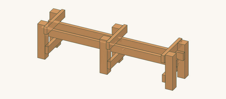
Loading the 3D view…
Drag to turn. Pinch or use + / − to zoom. The written step covers workholding and tool use.
Scroll or swipe the enlarged drawing to read its dimensions. Choose Fit to see the whole drawing again.
Finish the frame including the leg bottoms; the slats are coated flat on spacers before fitting.
Check: The finish is dry to the label standard and no raw end grain remains at the leg bottoms or slat ends.
- 13
Mark and drill the seat slats
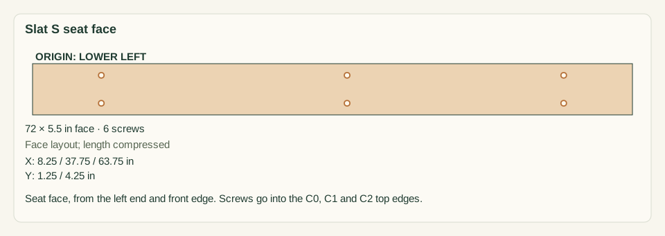
Lay each S seat face up. Measure from the left end and the front edge. Mark points at 8.25, 37.75 and 63.75 in along, each at 1.25 and 4.25 in across. Drill a clearance hole and countersink at each point, 18 holes in all, with the slat clamped to backing.
Close-up · Whole model shows the complete part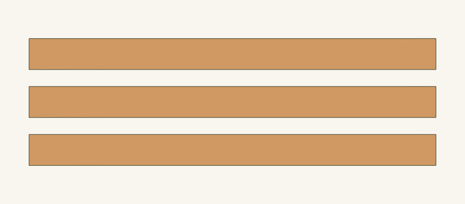
Loading the 3D view…
Drag to turn. Pinch or use + / − to zoom. The written step covers workholding and tool use.
Scroll or swipe the enlarged drawing to read its dimensions. Choose Fit to see the whole drawing again.
Each pair of holes falls on the center line of a cleat top edge.
Check: Each S shows six countersunk holes in matching positions and no breakout on the underside.
- 14
Fasten the seat slats
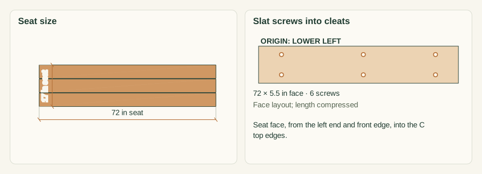
Set the frame back on the checked surface in its fitted position. Lay S0 with its front edge flush with the C front ends and its left end 4 in past the L0 outer face. Lay S1 and S2 behind it with 0.25 in spacers. Pilot into the C top edges through each hole and drive 18 screws, 6 per slat, keeping the S ends aligned.
Close-up · Whole model shows the complete part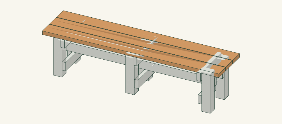
Loading the 3D view…
Drag to turn. Pinch or use + / − to zoom. The written step covers workholding and tool use.
Scroll or swipe the enlarged drawing to read its dimensions. Choose Fit to see the whole drawing again.
The slats overhang the legs 4 in at each end and are screwed only into the cleats.
Check: The seat measures 72 × 17 in, both gaps are 0.25 in, and every screw head sits just below the seat face.
- 15
Check that all six legs bear
Slide a strip of paper under each of the six feet in turn while a helper presses down on the seat directly above that station. Then press on each slat end and on the seat center and watch each foot. Do not drive wedges under a leg. If a center foot is loose, unscrew L2 and L3 and repeat the fitting and fastening steps.
Close-up · Whole model shows the complete part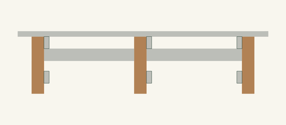
Loading the 3D view…
Drag to turn. Pinch or use + / − to zoom. The written step covers workholding and tool use.
Scroll or swipe the enlarged drawing to read its dimensions. Choose Fit to see the whole drawing again.
A paper strip pinched under each foot shows that leg is bearing.
Check: The paper is pinched under every foot, including L2 and L3, and the bench does not rock when any point is pressed.
- 16
Inspect before first use
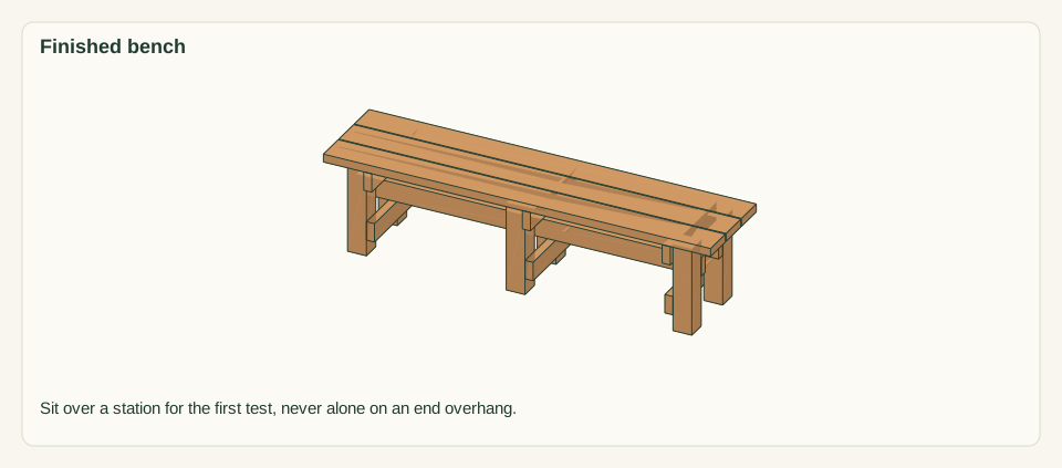
Before seated use, obtain the review of the frame, connections and stability listed under limits. Check all 54 screws for seated heads and no points breaking a surface. Check every C, T and R joint for gaps and every slat end for splits. Run a hand over the seat face and edges. Sit first over the center station, then over each end station, never alone on the 4 in end overhang.
Close-up · Whole model shows the complete partLoading the 3D view…
Drag to turn. Pinch or use + / − to zoom. The written step covers workholding and tool use.
Scroll or swipe the enlarged drawing to read its dimensions. Choose Fit to see the whole drawing again.
Every joint, screw head and slat end is checked before the first sitting test.
Check: No joint gap, split, protruding point, slat deflection you can see, or rocking is found.


05 / Keep it sound
Care
After the build
- Leave the bench where its center legs were fitted. If it must be moved, set it on a surface that passes the same straightedge check and repeat the center leg fitting.
- Use it as a seat for people sitting with their weight over or between the three stations. Keep it clear of sprinkler spray that wets the leg bottoms daily.
Check it each season
- Before each season, repeat the paper strip check under all six feet and check every screw head. Unload the bench before tightening or replacing a screw.
- Brush debris from the 0.25 in slat gaps, renew the finish per the product label, and replace any slat that splits rather than adding a screw beside the crack.
If something looks wrong
- Bench rocks on one corner
- Check the surface under that leg with the straightedge. Regrade or move the bench, then refit the center legs; do not use wedges.
- A center foot shows daylight
- Unload the bench, remove the 12 center screws, and repeat the center leg fitting with the feet pressed onto the surface.
- Seat dips between stations
- Stop using the bench and check that L2 and L3 bear. Replace a slat that stays bent after unloading.
- A rail or cleat joint opens
- Stop using the bench. Unload it, reclamp the joint flush, and replace any stripped screw with a new one in a fresh pilot.
- Slat splits at a screw
- Remove the slat and cut a replacement at 72 in. Pilot and countersink before driving its six screws.
Keep exploring