Garden storage · Guide 84
How to Build a Garden Tool Caddy with a Retained Handle
Make an open tool caddy with matched gabled ends, a hardwood dowel handle, and two mechanical retainers that keep the handle in position.
01 / See the shape
View the project
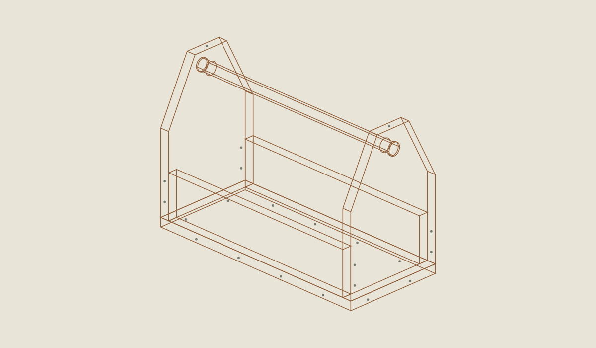
Loading the 3D view…
Drag to turn. Pinch or use + / − to zoom. The written step covers workholding and tool use.
Scroll or swipe the enlarged drawing to read its dimensions. Choose Fit to see the whole drawing again.
Portable garden tool caddy. Check the dimensions and build steps before cutting.
02 / Plan your build
Before you start
A useful caddy keeps a few hand tools together without becoming a bucket of exposed blades. This design has a low open box, two tall gabled ends, and a hardwood dowel that passes through both ends. Two retaining screws secure the dowel against sliding. The open body makes it easy to check that a tool is put away with its point covered rather than hidden under other equipment.
Use it for a small, selected set of guarded hand tools, gloves, labels, and ties. It is not a soil carrier, harvest crate, power-tool case, seat, ladder step, or a storage place for pesticides. Do not put an unguarded knife, pruning blade, or narrow pointed tool into an open compartment and assume the wooden sides make it safe.
Where it goes
Carry only tools with their guards fitted. Set it down on a stable surface and store it dry between uses.
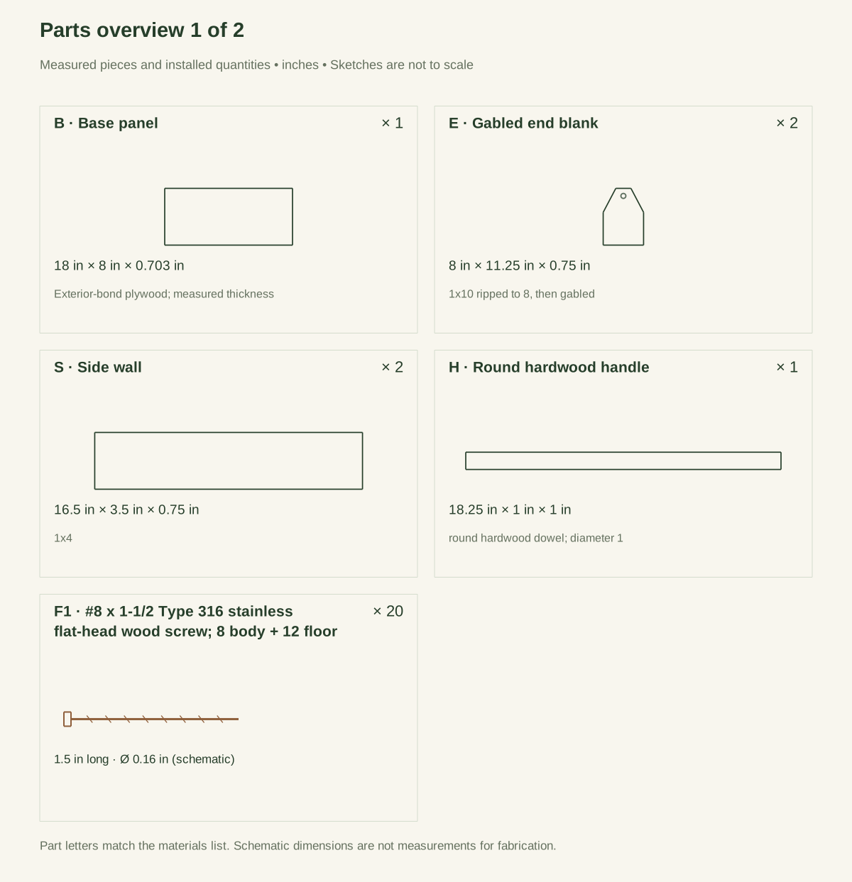
Footprint: 18 × 8 inches for the box. The handle sticks out 1/8 inch past each end, for 18-1/4 inches overall.
What to expect
Intermediate beginner: gabled profiles, large bores, and a mechanically retained round handle. Plan 2–4 working hours.
A planning estimate for the hands-on work, once the materials are bought and the tools are set up. It has not been timed on a finished build.
Check the spot
- Carry only tools with their guards fitted. Set it down on a stable surface and store it dry between uses.
- Measure the boards and hardware you actually bought before you cut, and set up a steady work surface. Keep other people back while you cut and drill.
Stop and check first if…
- Stop if a handle bore is loose, the dowel or upper web splits, or a retaining screw protrudes.
- Do not replace fitted tool guards with the box, or load sharp tools with exposed points above the rim.
- No carrying capacity is established; do not use as a seat, step, hanging carrier, or continuous outdoor-storage box.
- Carry with the handle over the center of the box, never by one gabled end. Lift only slightly at first and stop for movement, cracking, discomfort, or an unstable load; do not keep adding weight.
- Do not substitute a split broom handle or an unknown salvaged panel.
Work safely
- Use a tape, square, pencil, clamps, supported saw, jigsaw or coping saw for the gables, a drill with a suitable 1-inch wood-boring bit, pilot/clearance bits, countersink, driver, and abrasives. Drill the end boards while they are positively restrained on sacrificial backing. OSHA identifies a drill catching and spinning unsecured stock as a woodworking hazard; hold-downs, not a hand grip around a loose piece, are the control.
- Use appropriate eye, hearing, and dust protection. Restrain the dowel in a V-block or equivalent clamped cradle before drilling into it. Do not hold round stock in one hand while operating the drill with the other. This is a bench build: no excavation, wall fixing, electrical installation, or site modification is part of the plan.
- Stop if a handle bore is loose, the dowel or upper web splits, or a retaining screw protrudes.
- Do not replace fitted tool guards with the box, or load sharp tools with exposed points above the rim.
- No carrying capacity is established; do not use as a seat, step, hanging carrier, or continuous outdoor-storage box.
- Carry with the handle over the center of the box, never by one gabled end. Lift only slightly at first and stop for movement, cracking, discomfort, or an unstable load; do not keep adding weight.
- Do not substitute a split broom handle or an unknown salvaged panel.
Budget
We have not put a price on this one yet. Lumber and hardware prices change by store and season, so price the list under What you need at your local supplier before you buy.
03 / Gather and cut
What you need
Gabled end stock
1 board
Sound untreated pine 1 × 10; actual 0.75-inch thickness, ripped to 8-inch width. One 4-foot board.
Two 8 × 11.25-inch blanks before gable cuts. Use one template and preserve the 1-inch upper web above each handle bore.
Side-wall stock
1 board
Sound untreated pine 1 × 4; actual 0.75 × 3.5 inches. One 4-foot board.
Cut two 16.5-inch sides. Their ends fit between the gabled end boards.
Plywood floor
1 panel
Sound verified Exterior-bond plywood; reference thickness 0.703 inch. Blank yielding 18 × 8 inches after trimming.
Measure thickness before calculating overall height. The panel is supported by the fully assembled sides and ends.
Hardwood handle
1 dowel
Straight clear hardwood dowel, 1-inch actual diameter with a matched bore fit. One 36-inch dowel.
Finish at 18.25 inches; center for 1/8-inch overhang at each end. This is round stock, not a 1-inch-square bar.
Body and floor screws
20 screws
#8 × 1.5-inch Type 316 stainless flat-head wood screws. Package of at least 20.
Eight body screws plus twelve floor screws; keep these separate from the smaller handle retainers.
Handle retainers
2 screws
#6 × 1.5-inch Type 316 stainless flat-head wood screws. Package of at least two.
One vertical retainer through each end into the dowel, after a clamped trial in scrap; do not rely on a friction fit alone.
Tool guards
As needed guards
Manufacturer-supplied or appropriately fitted guards for each sharp tool. Selected for the actual tools.
Keep tools guarded individually; no internal divider, coating, glue, or carrying-load rating is included.
Cut list
| Piece | How many | Cut length | Note |
|---|---|---|---|
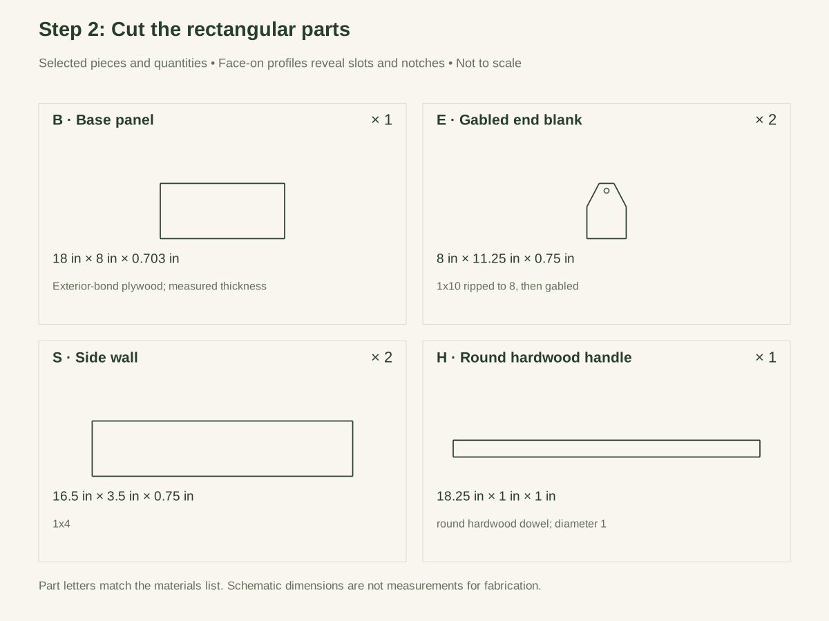
| B — Base panel | 1 | 18 in | Part B, cut from Exterior-bond plywood; measured thickness. Size: 18 × 8 × 0.703 in. Check the plan sheets for its reference edges and any shaped detail. |
| E — Gabled end blank | 2 | 8 in | Part E, cut from 1x10 ripped to 8, then gabled. Size: 8 × 11.25 × 0.75 in. Check the plan sheets for its reference edges and any shaped detail. |
| S — Side wall | 2 | 16.5 in | Part S, cut from 1x4. Size: 16.5 × 3.5 × 0.75 in. Check the plan sheets for its reference edges and any shaped detail. |
| H — Round hardwood handle | 1 | 18.25 in | Part H, cut from round hardwood dowel; diameter 1. Size: 18.25 in long; 1 in diameter. Check the plan sheets for its reference edges and any shaped detail. |
Tools
- Tape or rule, square, and pencil
- Clamps and stable supported work surface
- Suitable saw with its required guarding
- Drill/driver, selected-product pilot and clearance bits, and countersink
- Abrasives for hand-contact edges
- Suitable 1-inch wood-boring bit and sacrificial backing
- Coping saw or jigsaw suitable for the clamped gabled end profiles
Protective gear
- Eye protection for cutting and drilling; match other protection to the actual tool instructions.
- Appropriate hearing protection and wood-dust control for the selected cutting method.
04 / Put it together
Build steps
- 01
Check sections and choose a datum
Measure the actual 3/4-inch end and side stock and the plywood thickness. Mark the bottom and outward face of each end blank. Every gable and handle dimension below is measured from that bottom-left corner, with the board upright. A thinner end changes the between-end side length and handle fit; do not keep the original cuts when those measurements change.
Close-up · Whole model shows the complete part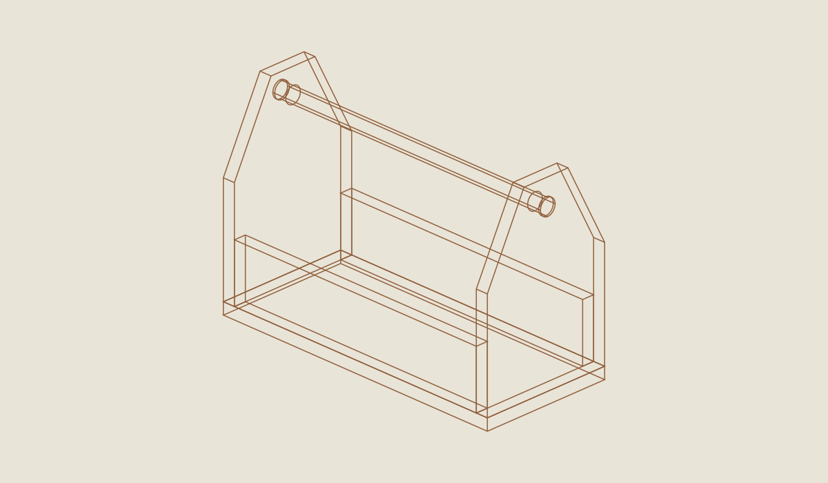
Loading the 3D view…
Drag to turn. Pinch or use + / − to zoom. The written step covers workholding and tool use.
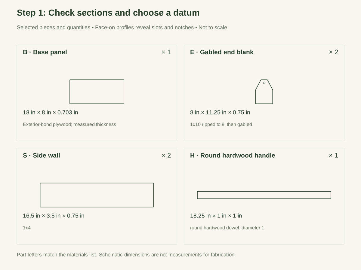
Scroll or swipe the enlarged drawing to read its dimensions. Choose Fit to see the whole drawing again.
Check: Actual stock sections match the plan, including floor thickness and dowel diameter; reference faces are labeled.
- 02
Cut the rectangular parts
Cut B to 18 × 8, two E blanks to 8 × 11-1/4, two S pieces to 16-1/2, and H to 18-1/4. Compare both end blanks and both side pieces face to face. The proposed shop target is matched like lengths within 1/32 inch and square seating edges. Reject defects in the upper end-board area that will carry the handle.
Close-up · Whole model shows the complete part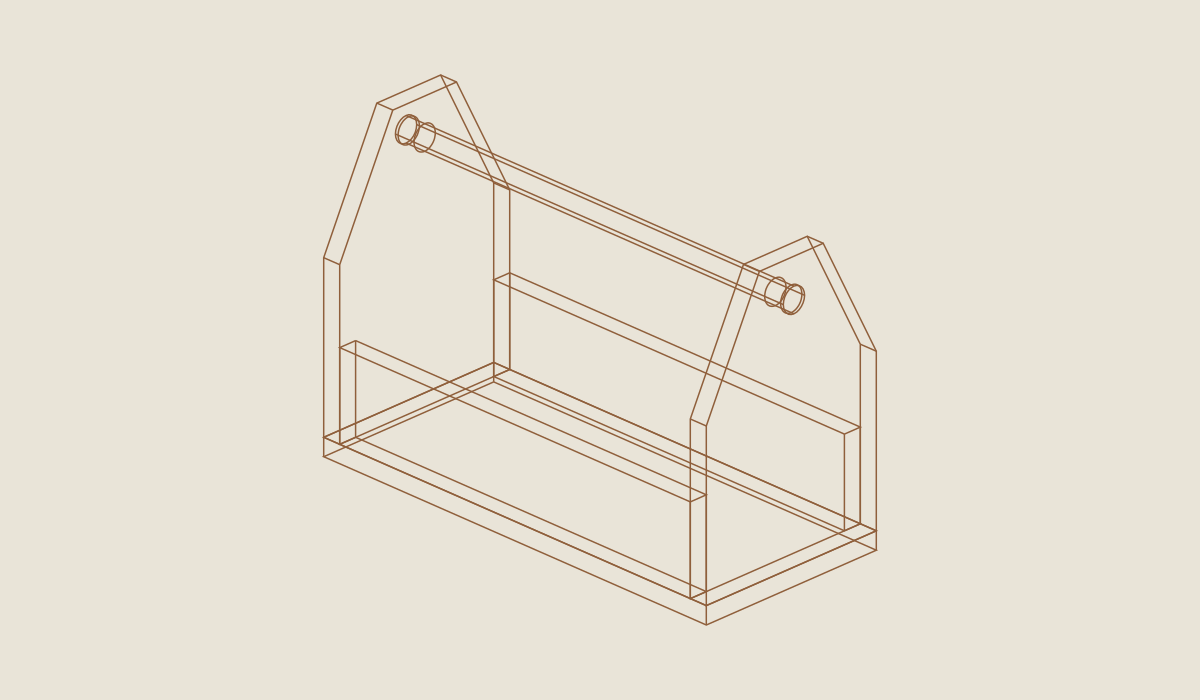
Loading the 3D view…
Drag to turn. Pinch or use + / − to zoom. The written step covers workholding and tool use.
Scroll or swipe the enlarged drawing to read its dimensions. Choose Fit to see the whole drawing again.
Check: The floor, two sides and two end blanks are cut with sound wood around both future handle bores.
- 03
Mark the gables
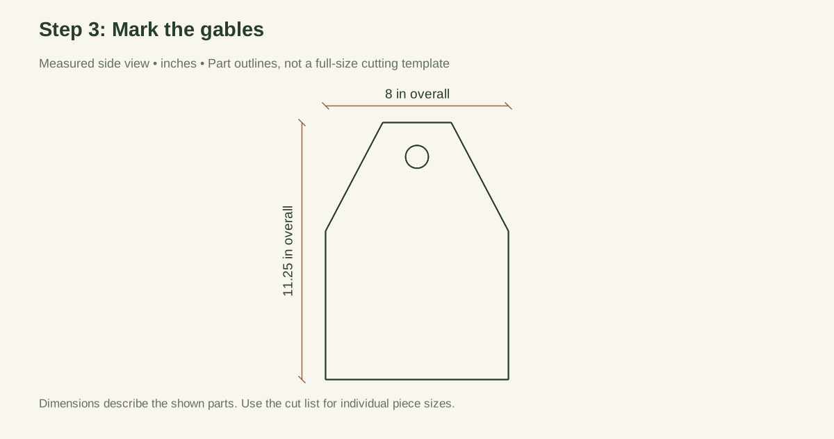
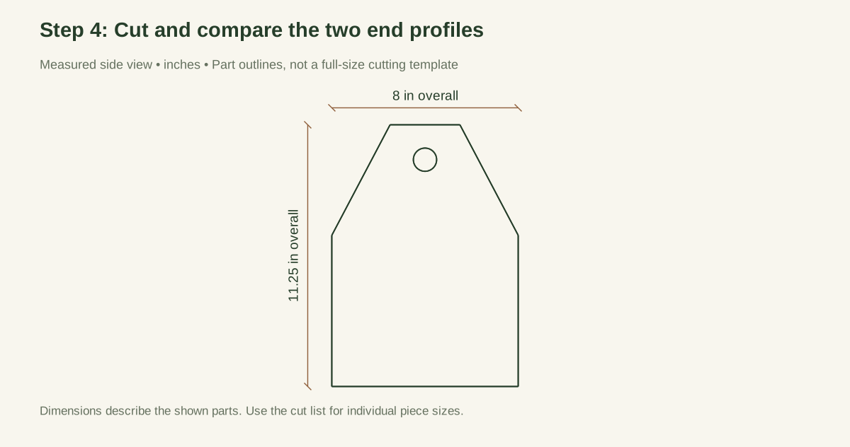
On each E blank, mark shoulder points at (0, 6-1/2) and (8, 6-1/2). Mark the ends of the flat top at (2-1/2, 11-1/4) and (5-1/2, 11-1/4). Connect each shoulder to the nearest top point. The retained outline has six vertices: bottom-left, bottom-right, right shoulder, right top, left top, left shoulder. The flat top is 3 inches wide.
Close-up · Whole model shows the complete part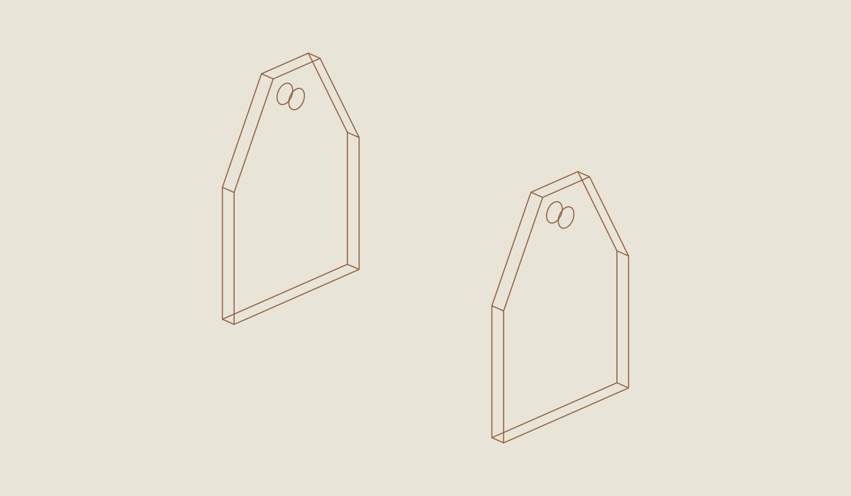
Loading the 3D view…
Drag to turn. Pinch or use + / − to zoom. The written step covers workholding and tool use.
Scroll or swipe the enlarged drawing to read its dimensions. Choose Fit to see the whole drawing again.
Check: Gable marks are mirrored around each end centerline and retain the 3-inch flat top.
- 04
Cut and compare the two end profiles
Clamp the blank with the waste supported and the blade path clear beneath it. Cut the sloping lines without levering the offcut against the retained upper section. Smooth the cuts, then place the ends together to check that they match. Do not sand away extra material around the future handle hole to disguise a mismatch.
Close-up · Whole model shows the complete part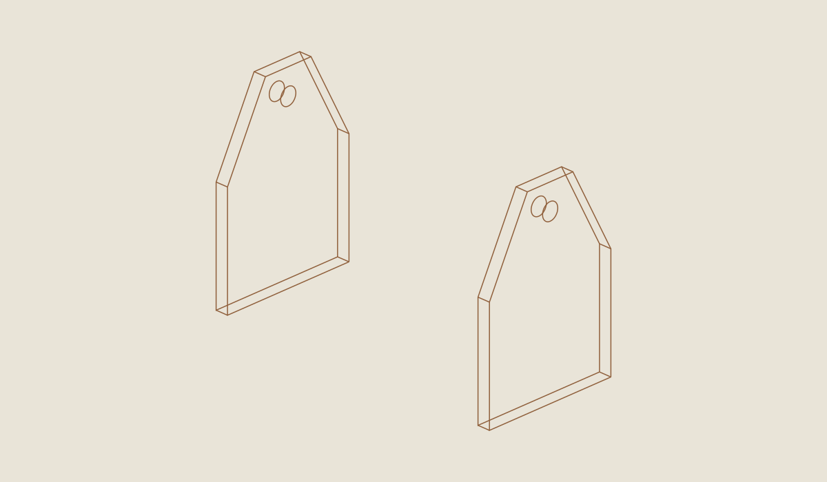
Loading the 3D view…
Drag to turn. Pinch or use + / − to zoom. The written step covers workholding and tool use.
Scroll or swipe the enlarged drawing to read its dimensions. Choose Fit to see the whole drawing again.
Check: The two cut end profiles coincide without excessive sanding; no split reaches a bore area.
- 05
Drill the handle bores
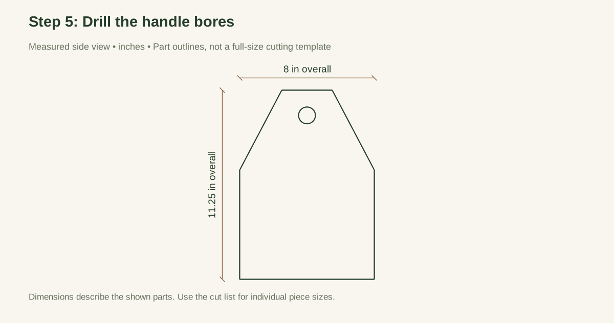
Mark the bore center at 4 inches from the end-board left edge and 9-3/4 inches above its bottom. Trial the actual dowel and 1-inch bit in scrap first. The dowel should slide through by hand with a close fit, not require hammering and not rattle visibly. If the nominal dowel or bore is not actually 1 inch, select a properly matched pair or revise the design.
Clamp each E over backing and bore perpendicular to its face. Keep the bit square so the two ends will not force the handle to bend. The wood above the bore is 1 inch from the bore's top to the flat upper edge. Inspect that web for breakout and cracks before assembly.
Close-up · Whole model shows the complete part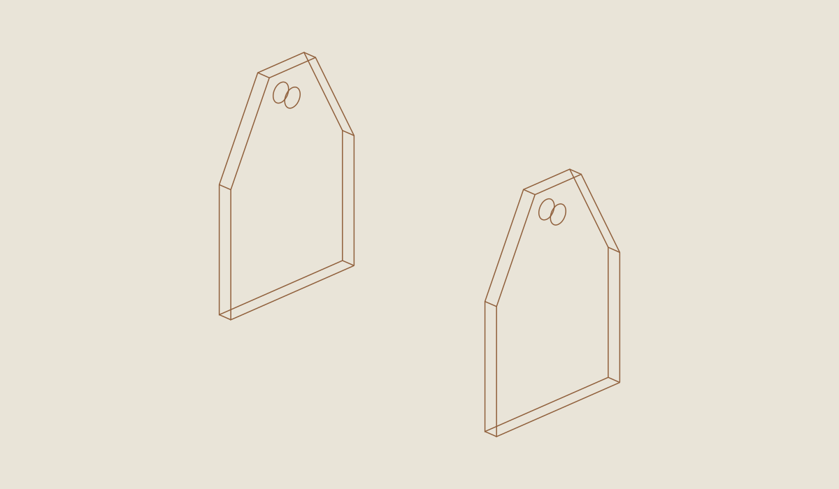
Loading the 3D view…
Drag to turn. Pinch or use + / − to zoom. The written step covers workholding and tool use.
Scroll or swipe the enlarged drawing to read its dimensions. Choose Fit to see the whole drawing again.
The handle bores must line up. Use the same reference edges on both ends.
Check: Both bores align at the same elevation, with the specified wood remaining above each one.
- 06
Clamp the sides between the ends
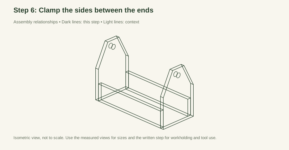
Set the ends parallel with their inside faces 16-1/2 inches apart. Fit S between them, flush with the lower and outside long edges. Check an 18 × 8 body footprint and a 16-1/2 × 6-1/2 clear floor. The ideal body diagonal is √(18² + 8²) = 19.698 inches. Match the two diagonals within 1/16 inch as the proposed shop target.
Close-up · Whole model shows the complete part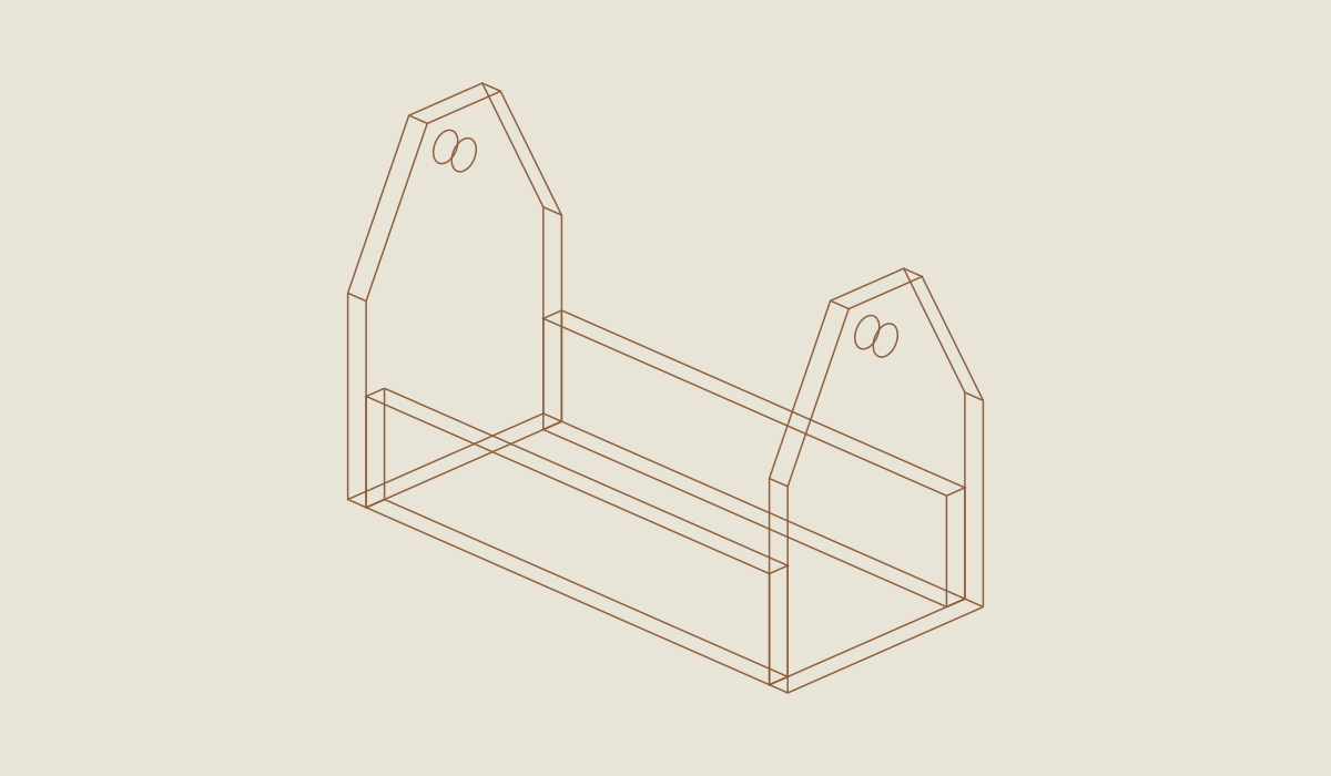
Loading the 3D view…
Drag to turn. Pinch or use + / − to zoom. The written step covers workholding and tool use.
Scroll or swipe the enlarged drawing to read its dimensions. Choose Fit to see the whole drawing again.
Check: Sides fit between ends and the two body diagonals agree within the 1/16-inch shop target.
- 07
Drill the eight body connections
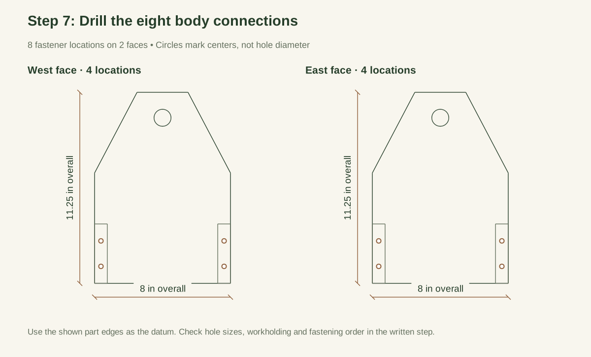
On each outward end face, mark screw lines 3/8 inch from the left and right edges, with holes 1 and 2-1/2 inches above the bottom. Each screw passes through E into the end of an S rail. For conventional #8 screws in this pine, begin a scrap trial with a 7/64-inch receiving pilot and an 11/64-inch clearance hole through E only; follow the purchased screw's instructions where different.
Countersink shallowly and keep each joint clamped during driving. Fit eight F1 screws. Stop for splitting, stripped receiving wood, or a corner that opens after the clamp is removed. Glue is not a substitute for a failed joint and is not included.
Close-up · Whole model shows the complete part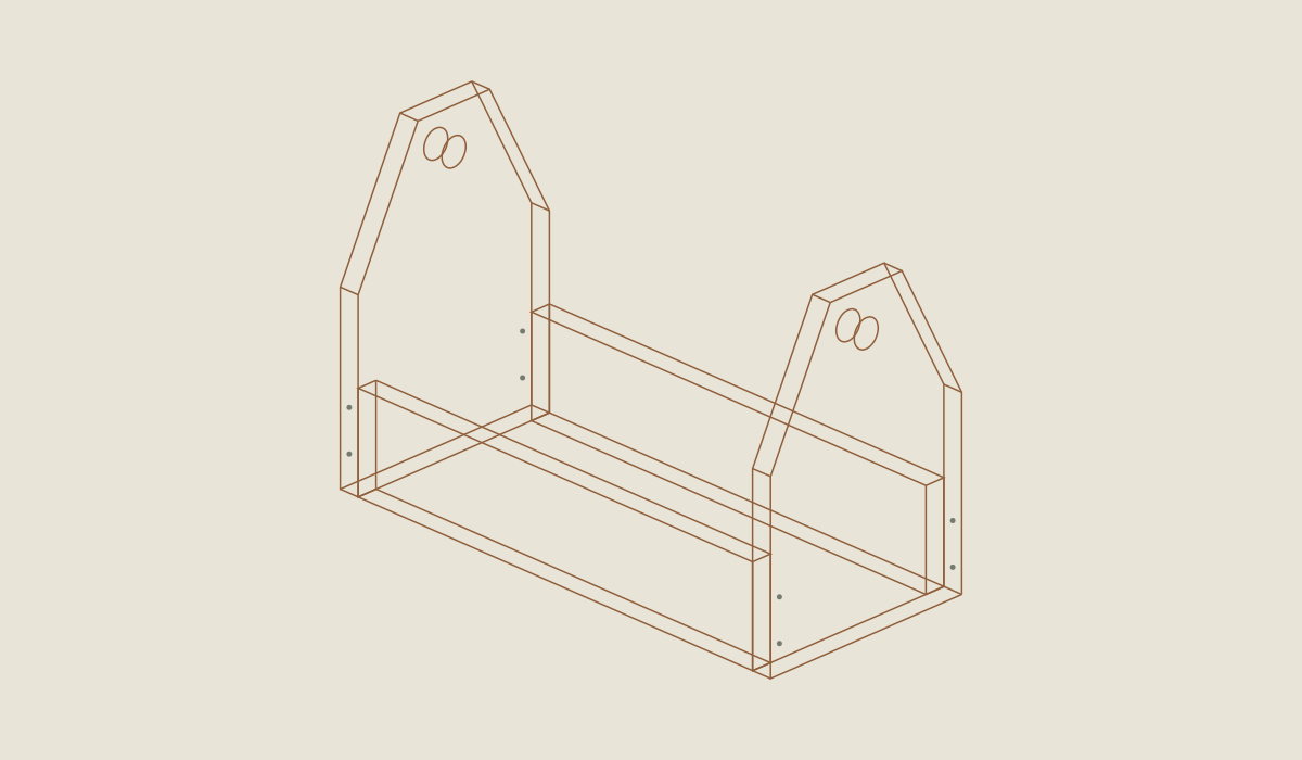
Loading the 3D view…
Drag to turn. Pinch or use + / − to zoom. The written step covers workholding and tool use.
Scroll or swipe the enlarged drawing to read its dimensions. Choose Fit to see the whole drawing again.
Check: All eight body screws enter sound receiving wood and no corner opens when clamps release.
- 08
Mark and attach the floor
Invert the body on a protected work surface and clamp B in place. Mark long-wall screw lines 3/8 inch from the long floor edges, at x stations 3, 7, 11, and 15 inches from the same 18-inch end. That gives eight screws. Add two under each end board at y stations 2 and 6 inches, on lines 3/8 inch from the short floor edges: four more.
Drill clearance through B and controlled receiving pilots into the wall lower edges. Install twelve F1 floor screws with underside heads flush. The total F1 count is now 20. Check the upright caddy for rocking and inspect the inside for exposed points before fitting the handle.
Close-up · Whole model shows the complete part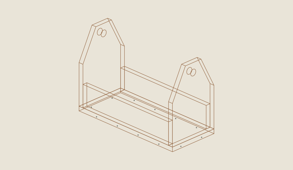
Loading the 3D view…
Drag to turn. Pinch or use + / − to zoom. The written step covers workholding and tool use.
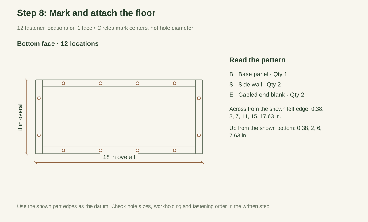
Scroll or swipe the enlarged drawing to read its dimensions. Choose Fit to see the whole drawing again.
Check: Twelve floor fixings enter the intended edges with no projecting point; the upright body does not rock.
- 09
Fit the dowel without forcing the ends
Slide H through both bores. Measure a 1/8-inch projection beyond each outer end face. Both ends should remain upright and parallel without being pulled together by the dowel. Mark the dowel's rotational position and projections while it is fitted. No adhesive is used to hide a loose bore.
Close-up · Whole model shows the complete part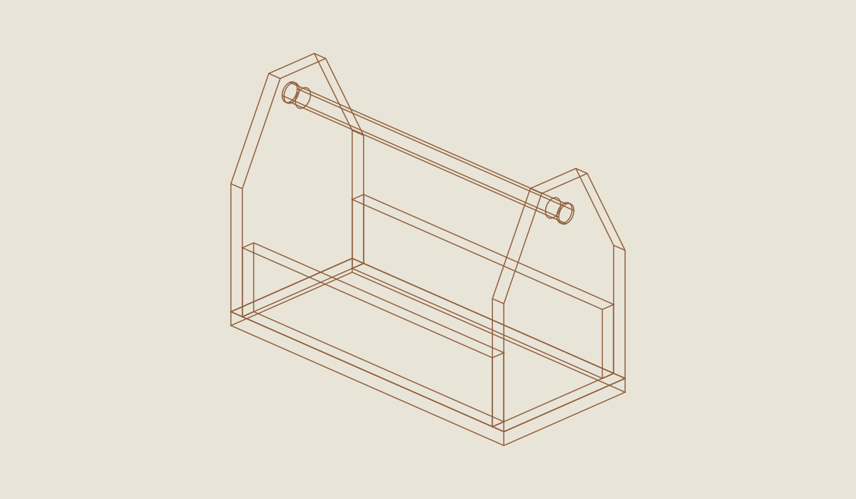
Loading the 3D view…
Drag to turn. Pinch or use + / − to zoom. The written step covers workholding and tool use.
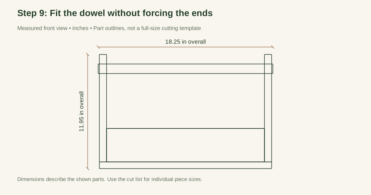
Scroll or swipe the enlarged drawing to read its dimensions. Choose Fit to see the whole drawing again.
Check: The real dowel enters both bores without spreading or pulling in the two end boards.
- 10
Drill the retaining screws on the top centerline
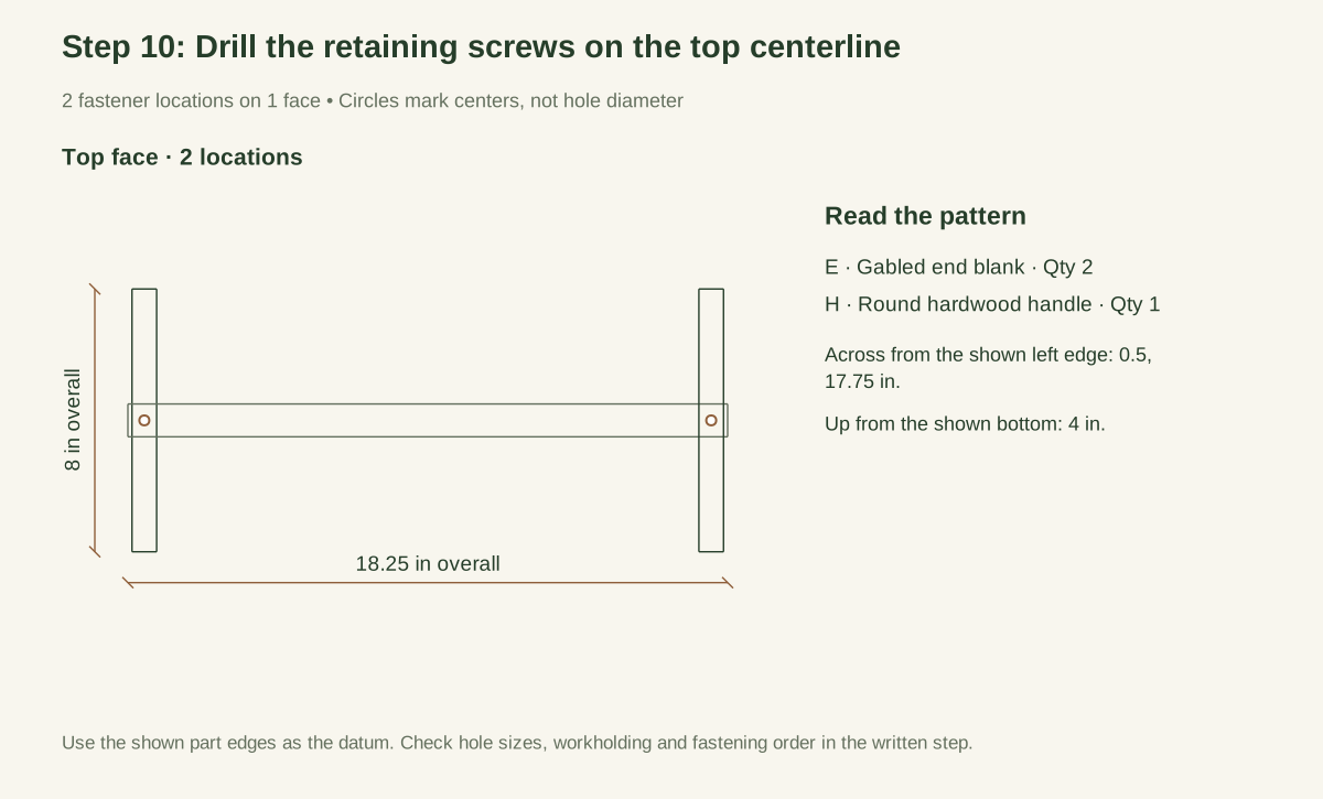
The retaining screw in each end is vertical, entering at the center of the 3-inch flat top and at the center of the 3/4-inch end-board thickness. Its path is aligned with the handle center. This plan uses a #6 × 1-1/2-inch screw: the first inch passes through the wood web above the bore, and the remaining half inch enters the dowel toward its center.
Clamp the assembly securely, restrain the dowel against turning, and mark this path before drilling. Trial the conventional #6 connection in scrap using a 5/64-inch receiving pilot and a 9/64-inch clearance through the end-board web only, subject to the actual product instructions. Use a depth stop; do not drill through the lower side of the dowel. Note the pilot size that worked.
Close-up · Whole model shows the complete part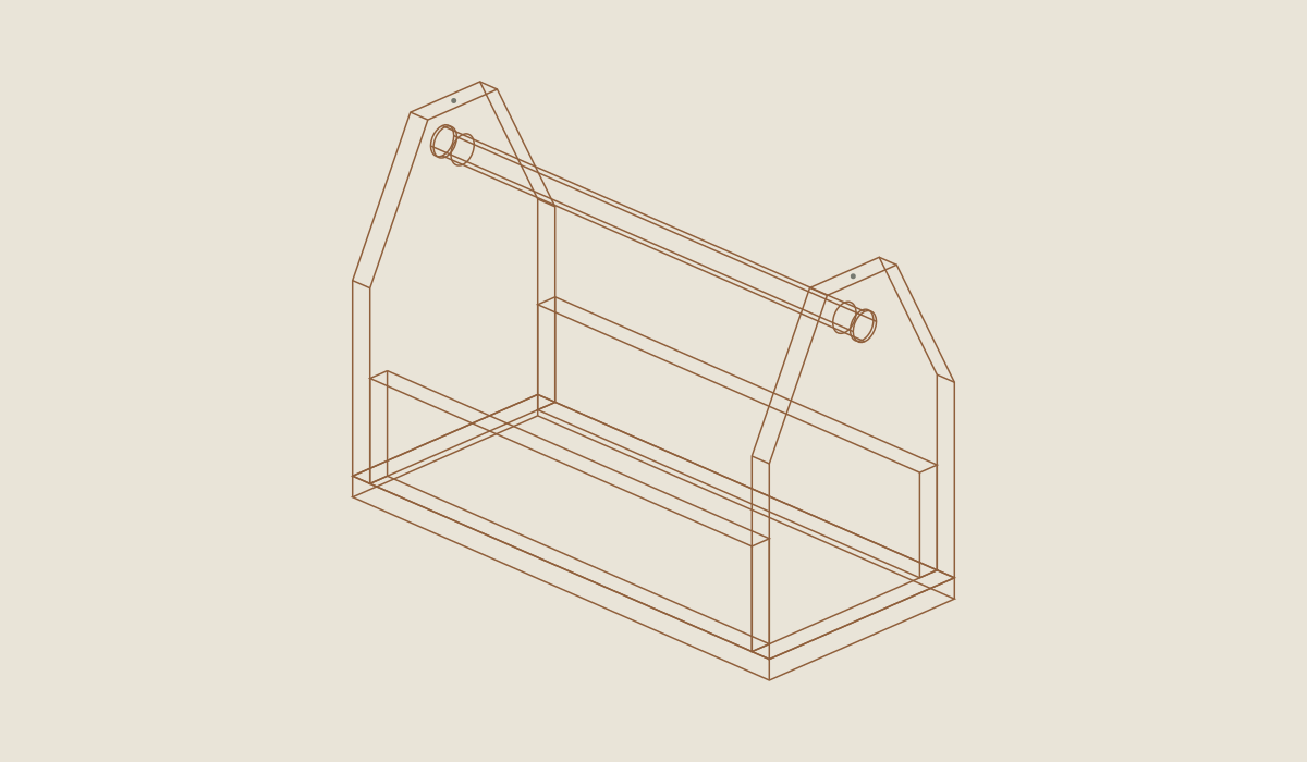
Loading the 3D view…
Drag to turn. Pinch or use + / − to zoom. The written step covers workholding and tool use.
Scroll or swipe the enlarged drawing to read its dimensions. Choose Fit to see the whole drawing again.
Check: Two retaining pilots are centered above the bores and stop inside the dowel, not through its lower side.
- 11
Install two F2 screws and recheck alignment
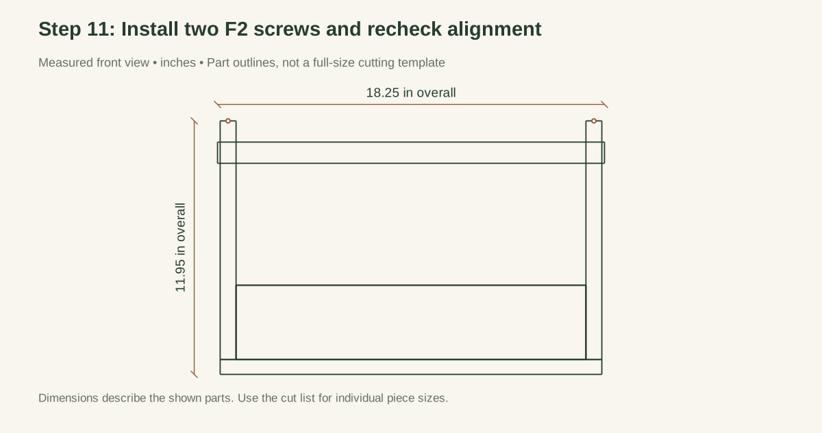
Seat the retaining heads flush with the end tops, using controlled torque. Do not deeply countersink into the narrow upper web. Check that the handle cannot slide axially or rotate freely by hand, and inspect both end webs for a new crack. A damaged bore, cracked web, or loose screw must be replaced before the caddy is carried; fitting a larger screw alongside the damage is not the prescribed repair.
Close-up · Whole model shows the complete part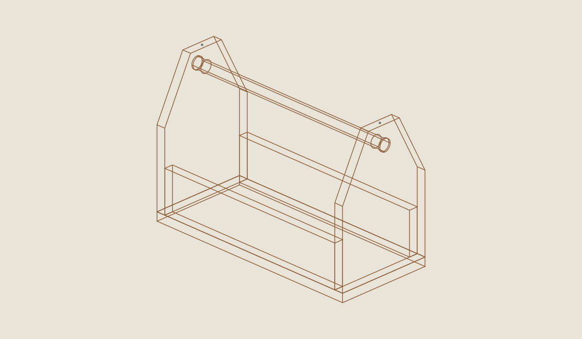
Loading the 3D view…
Drag to turn. Pinch or use + / − to zoom. The written step covers workholding and tool use.
Scroll or swipe the enlarged drawing to read its dimensions. Choose Fit to see the whole drawing again.
Check: Two #6 × 1-1/2-inch retainers seat; the handle does not slide or rotate freely and neither upper end web cracks.
- 12
Smooth and inspect the empty caddy
Ease the grip and dowel ends until there are no splinters, without reducing the shaft where it passes through the ends. Check all 22 installed screws, the underside, and every hand-contact edge. Inspect the empty body and both handle-retention points. Record the actual floor thickness, total height, dowel fit, and any change from the specified dimensions.
Close-up · Whole model shows the complete part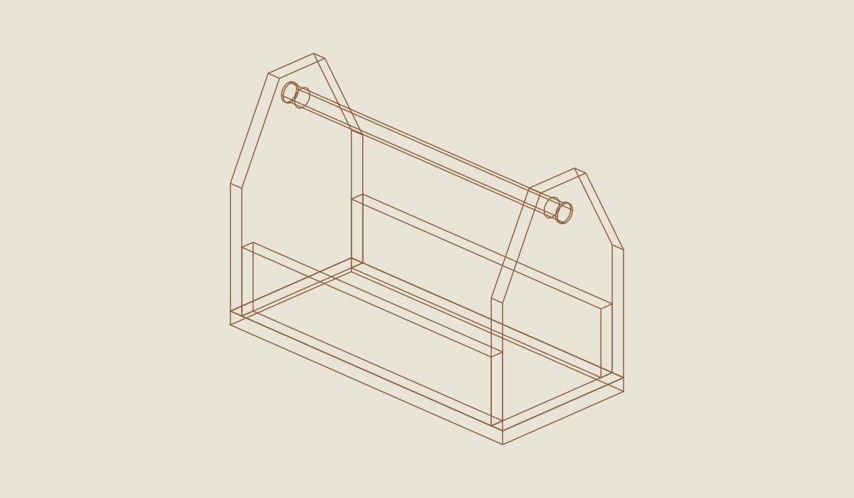
Loading the 3D view…
Drag to turn. Pinch or use + / − to zoom. The written step covers workholding and tool use.
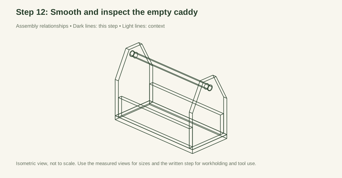
Scroll or swipe the enlarged drawing to read its dimensions. Choose Fit to see the whole drawing again.
Check: All twenty-two installed screws, handle-retention points and hand-contact edges are inspected while empty.
05 / Keep it sound
Care
After the build
- Fit guards to individual sharp tools before putting them into the caddy; check each tool can be removed without exposing a point.
- Confirm both handle retainers engage without splitting the wood or breaking out of the dowel before the first carry.
Check it each season
- First choose the tools, then their fitted guards. Place heavier objects low, keep the two sides reasonably balanced, and leave enough clear space around the handle for the whole gripping hand. Nothing sharp may project through a gap or above the rim without its own appropriate guard. Keep chemicals and food separate from the tool caddy.
- Start with only a few guarded tools, set on a safe surface. Lift only slightly and stop for movement, cracking, discomfort, or an unstable load. Do not keep increasing weight to discover the failure point. Carry with the handle over the center of the box, never by a single gabled end, and set it down gently.
- Empty after use, brush out grit, wipe only as needed, and dry fully before storage. Inspect the handle bores, top screws, corner joints, and floor attachments before the next outing. A dry-looking exterior does not prove that the floor edge or inside joint is sound.
- Use the harvest crate for produce and the seed organizer for dry seed packets. Keeping those jobs separate makes cleaning and inspection easier than asking one box to do everything.
If something looks wrong
- Handle slides or turns
- Check: Retaining screw, dowel pilot, bore fit. Fix: Stop carrying; unload and correct the actual failure.
- Crack above a bore
- Check: Grain defect, forcing, excessive screw torque. Fix: Replace the entire end and obtain review.
- Caddy tilts badly when lifted
- Check: Unbalanced or moving contents. Fix: Set down and reorganize guarded tools; do not counterbalance by overloading.
- Tool point reaches the floor or rim
- Check: Missing or unsuitable guard. Fix: Remove that tool until properly protected.
- Floor flexes or separates
- Check: Missed wall edge, loose screw, damaged panel. Fix: Empty and repair the full affected connection.
Keep exploring