Garden benches · Guide 50
Build a Garden Bench with Removable Seat Boards
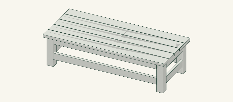
Build a 65-inch cedar garden bench with five 2 × 6 seat boards screwed to a braced 4 × 4 leg frame, so a worn board can be unscrewed and replaced.
01 / See the shape
View the project
Loading the 3D view…
Drag to turn. Pinch or use + / − to zoom. The written step covers workholding and tool use.

Scroll or swipe the enlarged drawing to read its dimensions. Choose Fit to see the whole drawing again.
The completed bench for the final inspection of joints, screws and seat surface.
02 / Plan your build
Before you start
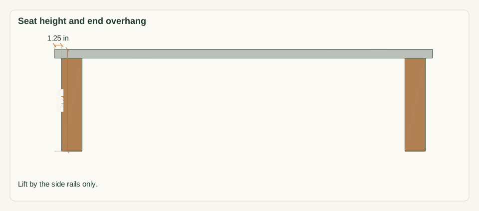
The frame is fully braced by itself: four legs, two upper and two lower side rails, two upper and two lower end rails and a center stretcher. The five seat boards add no bracing, so any one of them can be unscrewed and replaced without opening the frame. Every slat screw goes down through a clearance hole into the top of a rail, where it can be reached for removal. The design fails if the frame racks because a pocket joint was driven out of square or has loosened. It also fails if slat screws split a board end, if a replacement board differs from the measured 1.5 × 5.5 in section, or if someone sits on the 1.25 in end overhang outside the leg line.
Where it goes
Firm, level ground such as a paving or compacted pad, with clear space on both long sides and no drop or edge within reach of the seat. Keep the ground under the seat accessible for inspection.
Footprint: 65 × 28.5 in bench plus about 30 in clear on each long side and 12 in beyond each end for working access
What to expect
Measure accurately, make supported square cuts, drill pocket holes and drive screws without splitting. Plan 8–10 hours for a first build, including cutting, drilling, sanding and fitting the boards; finish drying time is extra.
A planning estimate for the hands-on work, once the materials are bought and the tools are set up. It has not been timed on a finished build.
Check the spot
- A firm, level surface at least 65 × 29 in with about 30 in clear on each long side. Confirm the ground does not slope and that nothing drops away within reach of the seat.
- Measure the usable stock before marking. Keep the assembly area flat and large enough to clamp work without reaching across a moving cutter.
Stop and check first if…
- Stop if a part splits, a screw strips, or the assembled bench rocks. Unload it before opening a joint.
- Stop if the frame racks when pushed by hand with one slat removed. Do not rely on the slats for bracing; get the frame reviewed first.
- Stop if a pocket screw tip breaks out of a rail face or a seat screw tip shows through a slat; change the screw length and recheck on scrap.
- Do not substitute stock of another section or change the length, height or slat spans without checking the affected parts and connections and obtaining fresh review.
Work safely
- Support 4 × 4 stock fully on both sides of each cut and clamp it. Never hold a short leg offcut by hand beside the blade.
- Clamp each rail in the pocket-hole jig before drilling and keep fingers clear of the stepped bit.
- Follow the saw, drill and finish manufacturer instructions. Keep guards in place and disconnect power before changing bits or blades.
- Lift the assembled bench with two people by the side rails, and keep hands clear of the gap between a rail and a leg.
Budget
We have not put a price on this one yet. Lumber and hardware prices change by store and season, so price the list under What you need at your local supplier before you buy.
03 / Gather and cut
What you need
L — Leg
4 pieces
Cedar 4 × 4; actual 3.5 × 3.5 in One 4 × 4 × 96 in board: 4 × 16 = 64 in plus about 0.5 in of kerf and 2 in of end trim leaves roughly 29 in of offcut.
Measure the actual section before cutting. Cut all four legs to the same length and chamfer the bottoms 0.25 in.
R — Upper side rail
2 pieces
Cedar 2 × 4; actual 1.5 × 3.5 in Counted with all 2 × 4 parts: four 96 in boards, laid out in the calculations.
Fits between the leg pairs, 55.5 in. Mark the top edge and the inside face before drilling.
B — Lower side rail
2 pieces
Cedar 2 × 4; actual 1.5 × 3.5 in Counted with all 2 × 4 parts: four 96 in boards.
Same length as R. It carries the leg frame against racking along the bench length, independent of the seat boards.
E — Upper end rail
2 pieces
Cedar 2 × 4; actual 1.5 × 3.5 in Counted with all 2 × 4 parts: four 96 in boards.
Fits between the front and rear leg of an end frame, 18 in. Its top is a seat support.
F — Lower end rail
2 pieces
Cedar 2 × 4; actual 1.5 × 3.5 in Counted with all 2 × 4 parts: four 96 in boards.
Same length as E. Ties the two legs of each end frame near the ground.
C — Center stretcher
1 piece
Cedar 2 × 4; actual 1.5 × 3.5 in Counted with all 2 × 4 parts: four 96 in boards.
Fits between the two R rails at mid-length and gives the slats a third support.
S — Removable seat slat
5 pieces
Cedar 2 × 6; actual 1.5 × 5.5 in Five 2 × 6 × 96 in boards, one slat per board: two 65 in slats need 130 in, which is more than 96 in. About 31 in of offcut per board.
Record the measured thickness and width. A replacement must match that section. Number the undersides 1–5 front to rear.
Pocket screws
36 items
#8 × 2.5 in coarse-thread pocket screws, stainless steel or a coating rated by the maker for exterior use in cedar Purchase at least 40; keep spares separate from the installed count.
Two per rail end at 18 rail ends. Set the jig and collar for 1.5 in stock. Test on scrap first and confirm no tip breaks out of a 1.5 in rail face.
Seat screws
24 items
#10 × 3 in stainless steel wood screws, flat or bugle head, rated for exterior use in cedar Purchase at least 30; keep spares separate from the installed count.
Clearance hole through the slat, pilot into the rail to the screw maker's chart, form a recess matching the selected head so the seated head is flush with the seat face. Engagement into the rail is 1.5 in.
Cut list
| Piece | How many | Cut length | Note |
|---|---|---|---|
| L — Leg | 4 | 16 × 3.5 × 3.5 in | Finished length × width × thickness; square ends unless the detail says otherwise. |
| R — Upper side rail | 2 | 55.5 × 3.5 × 1.5 in | Finished length × width × thickness; square ends unless the detail says otherwise. |
| B — Lower side rail | 2 | 55.5 × 3.5 × 1.5 in | Finished length × width × thickness; square ends unless the detail says otherwise. |
| E — Upper end rail | 2 | 18 × 3.5 × 1.5 in | Finished length × width × thickness; square ends unless the detail says otherwise. |
| F — Lower end rail | 2 | 18 × 3.5 × 1.5 in | Finished length × width × thickness; square ends unless the detail says otherwise. |
| C — Center stretcher | 1 | 22 × 3.5 × 1.5 in | Finished length × width × thickness; square ends unless the detail says otherwise. |
| S — Removable seat slat | 5 | 65 × 5.5 × 1.5 in | Finished length × width × thickness; square ends unless the detail says otherwise. |
Tools
- Tape or rule, combination square and sharp pencil
- Saw suited to 4 × 4 stock with a guide or support for square cuts
- Pocket-hole jig with drill collar and stepped bit
- Drill/driver, pilot and clearance bits, countersink and depth stop for the chosen screws
- Clamps, a flat bench and 0.25 in spacers
- 48 in level, straightedge, 120-grit sanding block and dust brush
Protective gear
- Eye protection during cutting, drilling and sanding
- Hearing protection and dust control appropriate to the actual tools
- Closed footwear; keep loose clothing and gloves away from rotating cutters
04 / Put it together
Build steps
- 01
Confirm the site and intended use
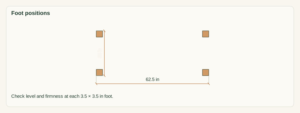
Choose a firm, level surface at least 65 × 29 in with about 30 in clear on each long side. Lay a straightedge and level across the four foot positions within a 62.5 × 25 in outside footprint. Look for roots, drops and edges within reach of the seat.
Close-up · Whole model shows the complete part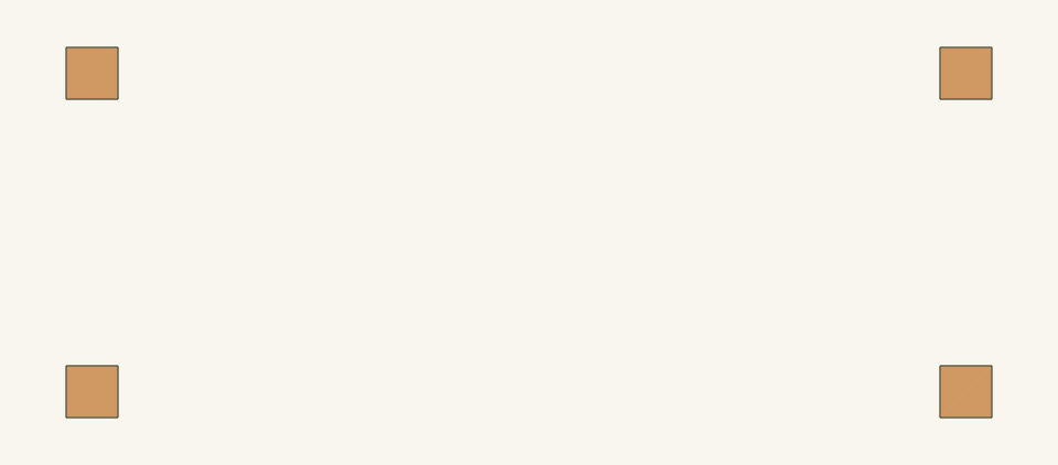
Loading the 3D view…
Drag to turn. Pinch or use + / − to zoom. The written step covers workholding and tool use.
Scroll or swipe the enlarged drawing to read its dimensions. Choose Fit to see the whole drawing again.
Planning reference only: the four foot positions the ground must support. The bench is not built at this step.
Check: The four 3.5 × 3.5 in foot positions are firm and level, and nothing drops away or sags near the seat.
- 02
Inspect and measure the stock
Measure every board at both ends and the middle. The 4 × 4 must be 3.5 × 3.5 in, the 2 × 4 boards 1.5 × 3.5 in and the 2 × 6 boards 1.5 × 5.5 in. Reject boards with splits within 6 in of an end, twist, loose knots or bow over 0.125 in. Write the measured 2 × 6 thickness and width on a tag.
Close-up · Whole model shows the complete part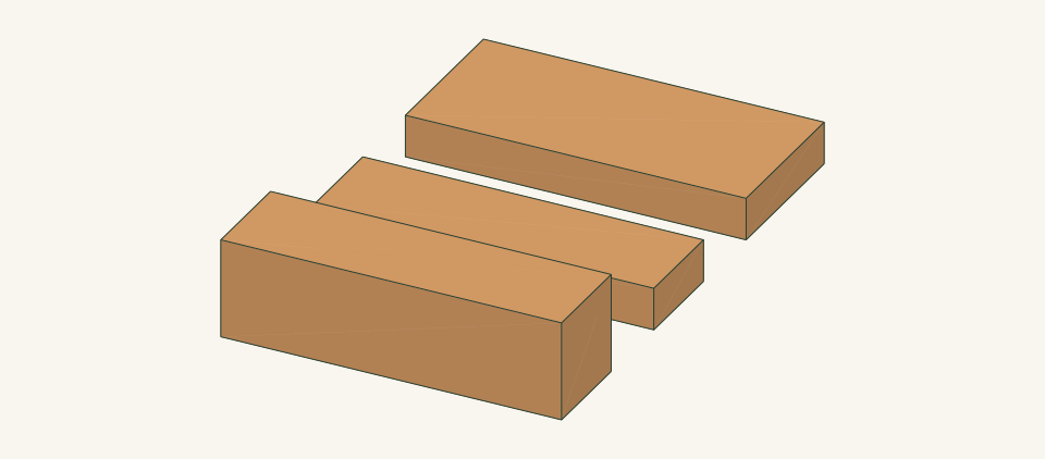
Loading the 3D view…
Drag to turn. Pinch or use + / − to zoom. The written step covers workholding and tool use.
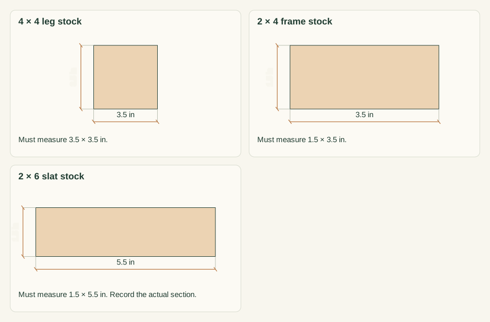
Scroll or swipe the enlarged drawing to read its dimensions. Choose Fit to see the whole drawing again.
The three stock sections to measure before any cut.
Check: All sections match the parts table and the 2 × 6 section is recorded. If not, work stops until the cut lengths are reworked for the stock in hand.
- 03
Cut the legs and frame rails
Square one end of each board and measure from it. From the 4 × 4 cut four legs L at 16 in. From 2 × 4 board 1 cut R at 55.5, E at 18 and E at 18 in. From board 2 cut R at 55.5, F at 18 and F at 18 in. From board 3 cut B at 55.5 and C at 22 in. From board 4 cut B at 55.5 in. Label every part, mark top edges and chamfer the leg bottoms 0.25 in.
Close-up · Whole model shows the complete part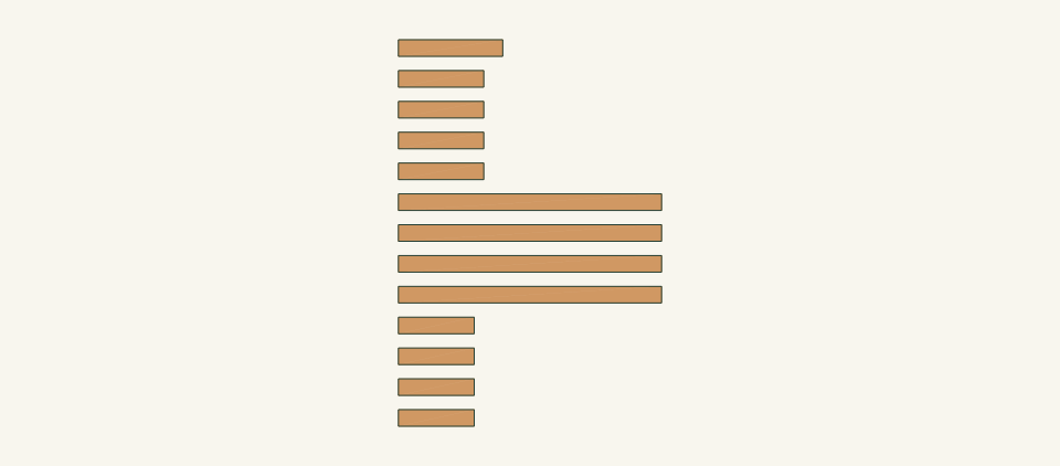
Loading the 3D view…
Drag to turn. Pinch or use + / − to zoom. The written step covers workholding and tool use.
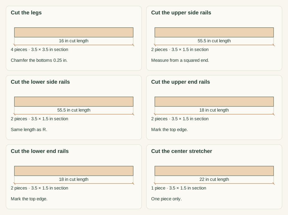
Scroll or swipe the enlarged drawing to read its dimensions. Choose Fit to see the whole drawing again.
The frame parts laid out loose as cut from the 4 × 4 and 2 × 4 boards.
Check: Paired parts match within 0.0625 in and every cut end is square to its face and edge.
- 04
Cut the seat slats
Square one end of each 2 × 6 board, then cut one slat S at 65 in from each of the five boards. Choose the better face as the seat face and mark it. Ease the seat-face edges and the cut ends 0.125 in with a block or round-over bit.
Close-up · Whole model shows the complete part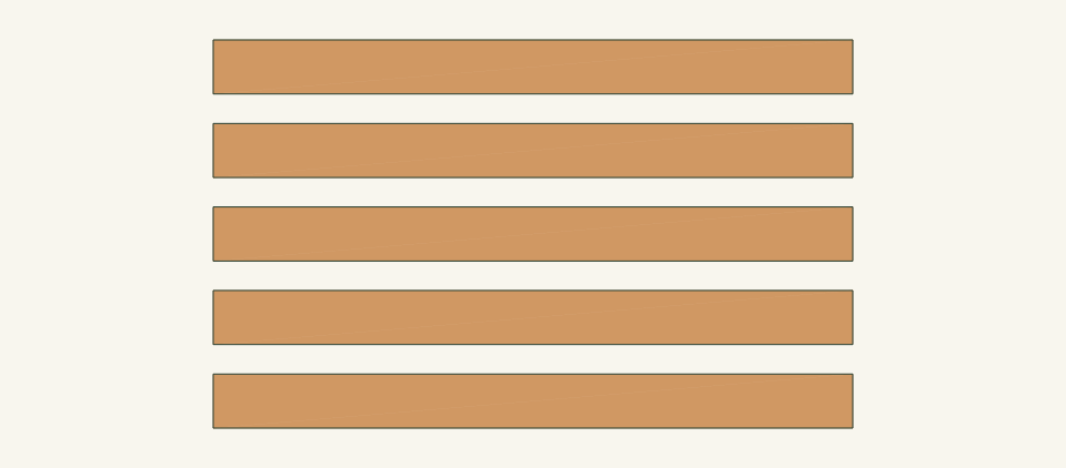
Loading the 3D view…
Drag to turn. Pinch or use + / − to zoom. The written step covers workholding and tool use.
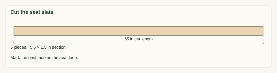
Scroll or swipe the enlarged drawing to read its dimensions. Choose Fit to see the whole drawing again.
The five slats laid out loose, one cut from each 2 × 6 board.
Check: All five slats match within 0.0625 in, lie flat face to face and have no splinters on the seat face.
- 05
Drill the pocket holes
Set the jig and drill collar for 1.5 in stock per the jig instructions. Clamp each rail in the jig. On R, B, E and F drill two holes at each end, 0.75 and 2.75 in below the top edge, on the face that will face the inside of the bench. On C drill the same two holes at each end on the face toward the left end. That is 36 holes in total.
Close-up · Whole model shows the complete part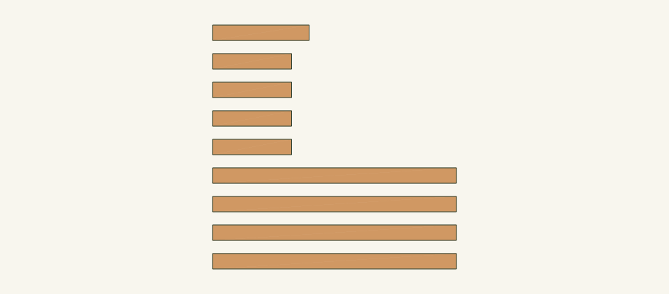
Loading the 3D view…
Drag to turn. Pinch or use + / − to zoom. The written step covers workholding and tool use.
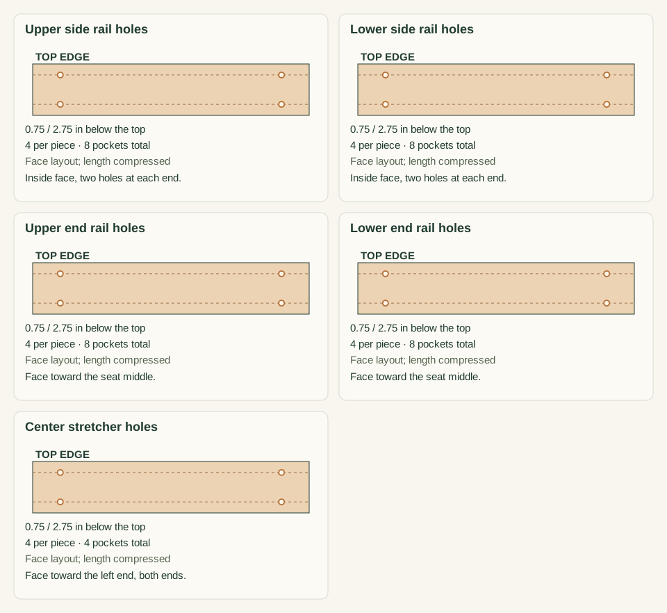
Scroll or swipe the enlarged drawing to read its dimensions. Choose Fit to see the whole drawing again.
Pocket holes on the rails, laid out loose before any assembly.
Check: Count 36 holes, each on the correct face, with no hole breaking through a top or bottom edge.
- 06
Assemble the two end frames
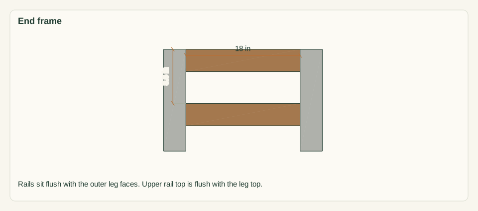
On a flat bench lay two legs L with 18 in between their inner faces. Clamp E between them, top edge flush with the leg tops and outer face flush with the leg outer faces, pocket holes facing the seat middle. Clamp F with its top edge 8.5 in below the leg tops. Drive 4 screws into each rail. Repeat for the second end frame. That is 16 screws.
Close-up · Whole model shows the complete part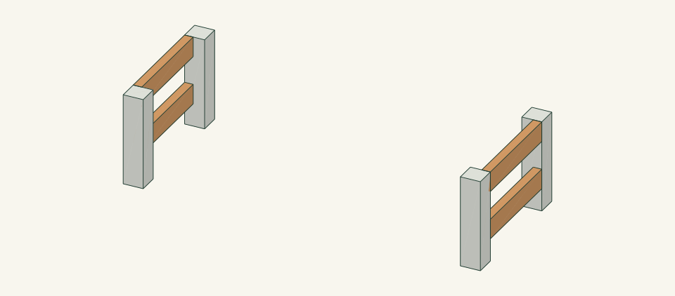
Loading the 3D view…
Drag to turn. Pinch or use + / − to zoom. The written step covers workholding and tool use.
Scroll or swipe the enlarged drawing to read its dimensions. Choose Fit to see the whole drawing again.
Two end frames, each a front and rear leg joined by an upper and a lower end rail.
Check: Each end frame measures 25 in wide by 16 in high outside and its diagonals both read 29.68 in within 0.0625 in.
- 07
Join the side rails and stretcher
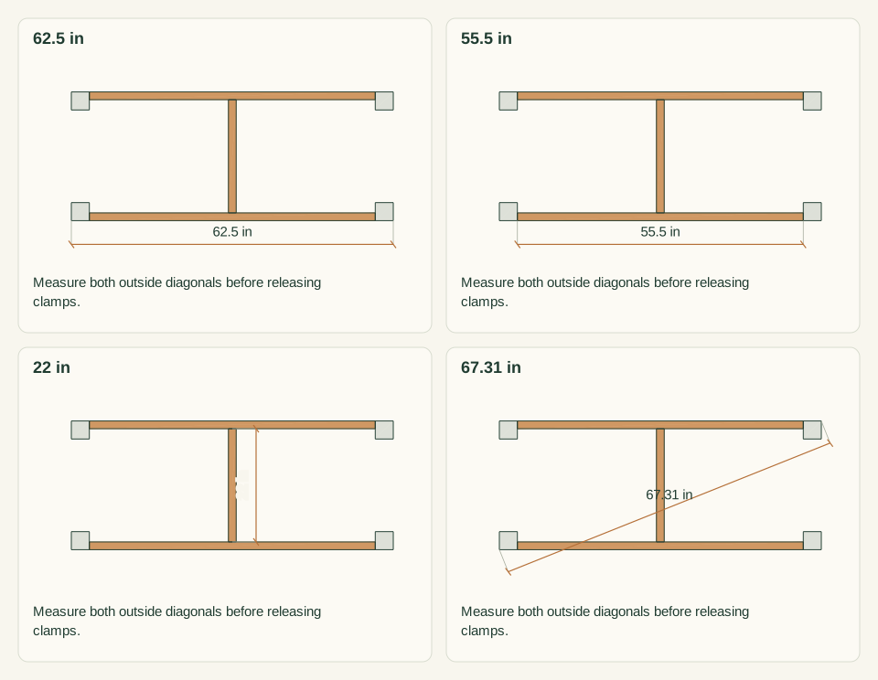
Stand the end frames upright 55.5 in apart between inner leg faces, with a helper holding them. Clamp each R between the legs with its top edge flush to the leg tops and its outer face flush to the leg outer faces. Clamp each B with its top edge 8.5 in below the leg tops. Drive 8 screws into each pair. Clamp C between the R rails with its left face 30.5 in from the outer face of the left legs and drive 4 screws.
Close-up · Whole model shows the complete part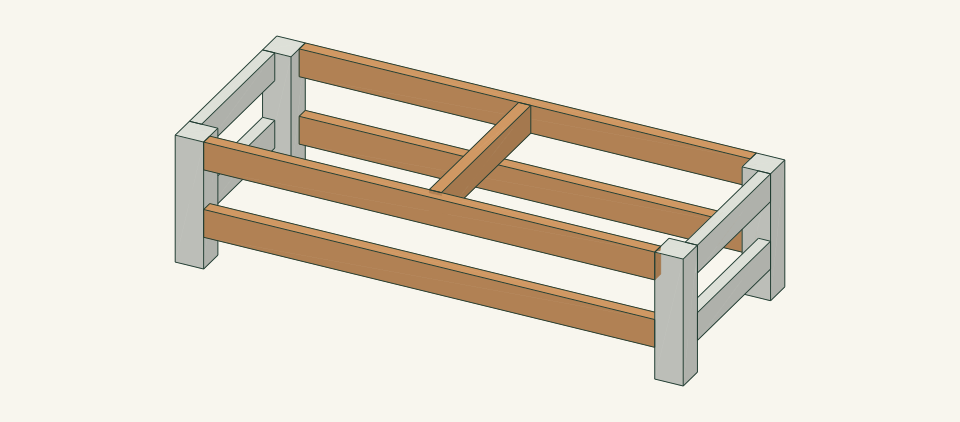
Loading the 3D view…
Drag to turn. Pinch or use + / − to zoom. The written step covers workholding and tool use.
Scroll or swipe the enlarged drawing to read its dimensions. Choose Fit to see the whole drawing again.
Side rails and the center stretcher join the end frames into one braced frame.
Check: Top outside diagonals both read 67.31 in within 0.125 in, all four feet touch the bench and no screw tip shows.
- 08
Sand and finish the parts
Sand all exposed faces to 120 grit and remove the dust. Ease sharp edges 0.125 in. Cedar may be left unfinished. If an exterior finish is used, coat every face of the frame and all faces of all five slats, including undersides and leg end grain, and follow the product label for drying time.
Close-up · Whole model shows the complete part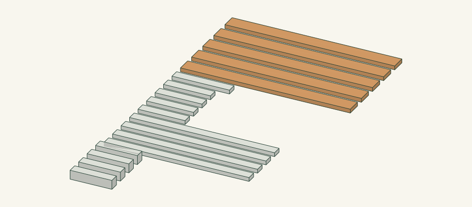
Loading the 3D view…
Drag to turn. Pinch or use + / − to zoom. The written step covers workholding and tool use.
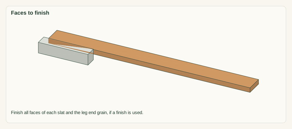
Scroll or swipe the enlarged drawing to read its dimensions. Choose Fit to see the whole drawing again.
Slats stay separate from the frame so every face, including undersides and ends, can be sanded and finished.
Check: Surfaces and end grain are smooth to the hand. If a finish was applied, it is fully dry to the product label before assembly.
- 09
Fit the slats and drill the screw holes
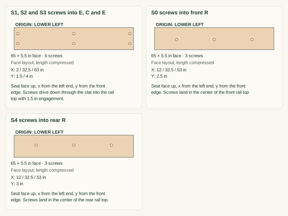
Lay S0 to S4 on the frame, front to rear, with 0.25 in spacers between them. Set the slat ends 1.25 in past the leg outer faces and S0 1.75 in in front of the front leg faces. Number each underside 1–5 and mark the left end. Mark the screw centers from the measured patterns. Drill clearance holes through the slats, pilot the rails to the screw maker's chart and form the matching head recess so the seated head finishes flush.
Close-up · Whole model shows the complete part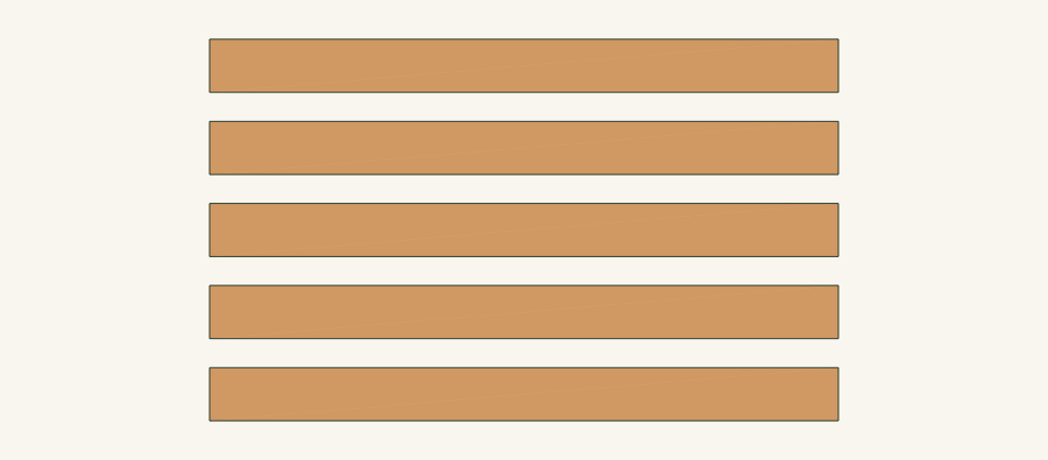
Loading the 3D view…
Drag to turn. Pinch or use + / − to zoom. The written step covers workholding and tool use.
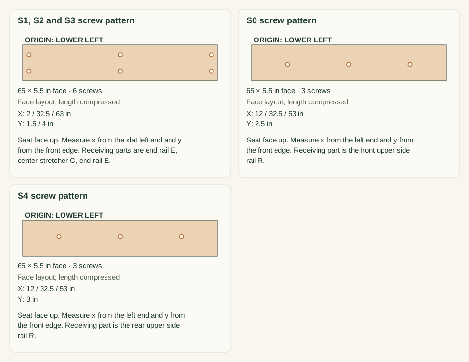
Scroll or swipe the enlarged drawing to read its dimensions. Choose Fit to see the whole drawing again.
Seat screw positions on the slat top faces, shown loose in numbered order.
Check: There are 24 marked and drilled points, each centered over a rail top, and none is closer than 1.5 in to a slat end.
- 10
Fasten the seat slats
Keep the 0.25 in spacers in place. Drive the 24 screws #10 × 3 in square into the rails, starting at the middle of each slat and working toward the ends. Stop each screw when the head is flush with the seat face. Pull the spacers out when all slats are fixed.
Close-up · Whole model shows the complete part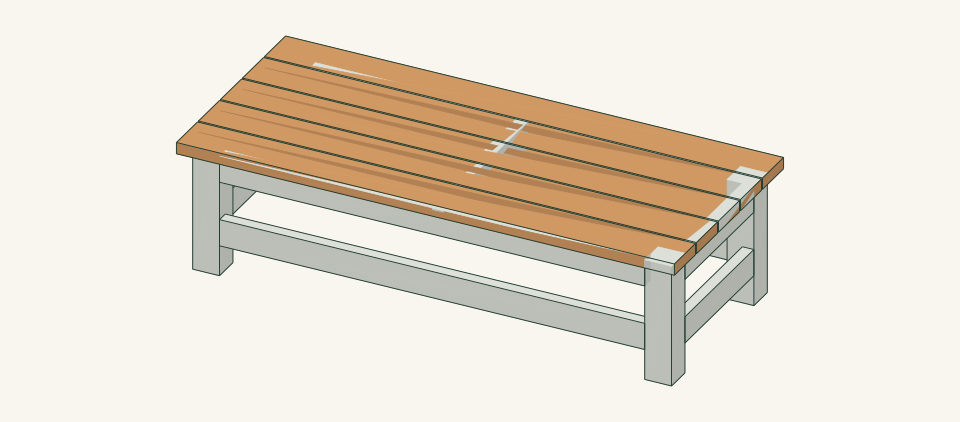
Loading the 3D view…
Drag to turn. Pinch or use + / − to zoom. The written step covers workholding and tool use.
Scroll or swipe the enlarged drawing to read its dimensions. Choose Fit to see the whole drawing again.
The five slats are fixed to the rail tops with the complete 24-screw pattern.
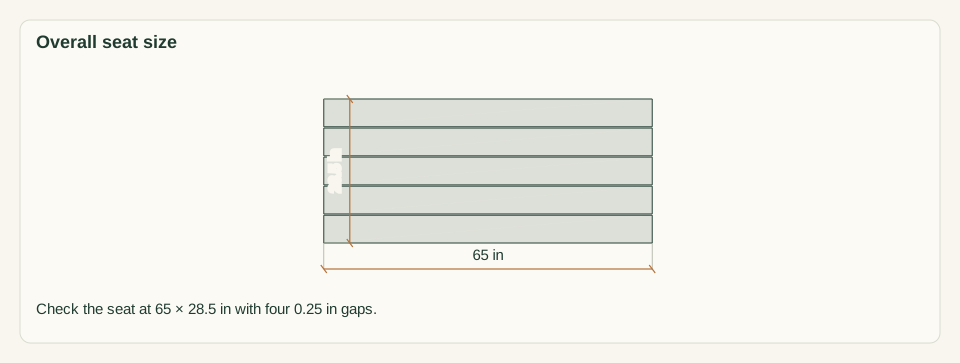
Check: The seat measures 65 × 28.5 in, all four gaps are 0.25 in and no slat splits at a screw.
- 11
Place and level the bench
With two people, lift the bench by the R rails, not by a slat end, and set it on the checked site. Press down on each seat corner in turn without sitting. Do not use loose wedges under a leg. Move the bench or regrade the ground if it rocks.
Close-up · Whole model shows the complete part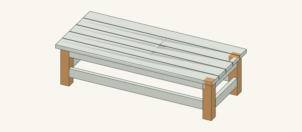
Loading the 3D view…
Drag to turn. Pinch or use + / − to zoom. The written step covers workholding and tool use.
Scroll or swipe the enlarged drawing to read its dimensions. Choose Fit to see the whole drawing again.
The finished bench set on the checked site, with the four feet carrying it.
Check: All four legs bear on the ground and the bench does not rock when each corner is pressed.
- 12
Practice replacing one slat
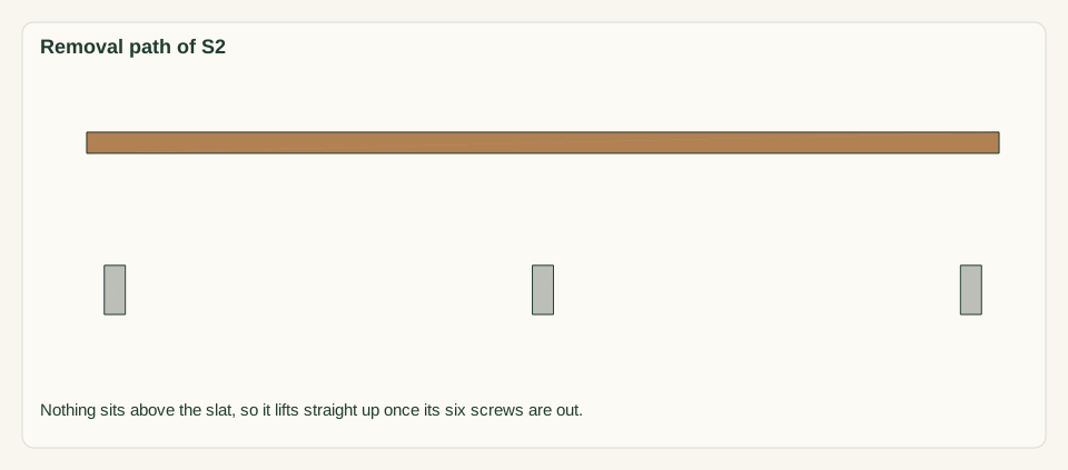
Back out the six screws of S2. Lift it straight up and look at each rail pilot hole for crushed or stripped wood. Push the frame gently by hand to confirm it stays rigid with S2 off. Set S2 back in the same position and refit it with the same six screws, heads flush with the face.
Close-up · Whole model shows the complete part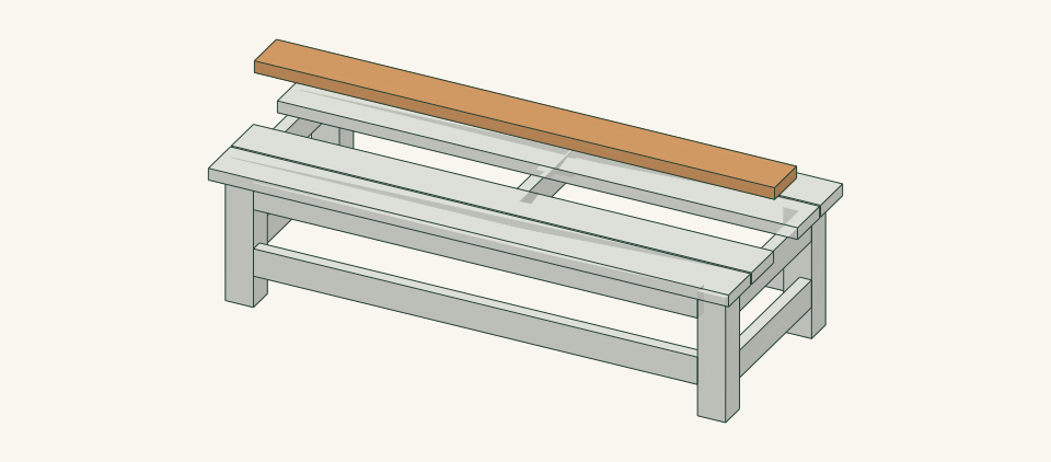
Loading the 3D view…
Drag to turn. Pinch or use + / − to zoom. The written step covers workholding and tool use.
Scroll or swipe the enlarged drawing to read its dimensions. Choose Fit to see the whole drawing again.
S2 is shown 8 in above its seat position only to show the straight vertical removal path; the real slat is lifted just clear.
Check: The frame does not rack with S2 off, and the screws re-seat firmly without spinning or splitting the slat.
- 13
Inspect before first use
Before seated use, obtain the frame, connection, racking and tipping review identified under limits. Check all 36 frame screws and 24 seat screws for seated heads and no tips through a surface. Check every leg and rail joint for gaps and every slat end for splits. Run a hand over the seat face and edges. Measure the top diagonals again. Sit near the center first, then test each end between the legs.
Close-up · Whole model shows the complete partLoading the 3D view…
Drag to turn. Pinch or use + / − to zoom. The written step covers workholding and tool use.
Scroll or swipe the enlarged drawing to read its dimensions. Choose Fit to see the whole drawing again.
The completed bench for the final inspection of joints, screws and seat surface.
Check: No joint gap, split, protruding point or rocking is found, and the diagonals still read 67.31 in within 0.125 in.


05 / Keep it sound
Care
After the build
- Place the bench on firm, level ground and press each seat corner before use. Treat it as unreviewed seating until the reviews named in the limits are closed.
- To replace a slat, cut a new 65 in board from stock measured at 1.5 × 5.5 in, copy the face pattern for that slat position, and refit with the same #10 × 3 in screws and 0.25 in gaps.
Check it each season
- Inspect all joints, seat screws and slat ends before each season of use and after any rocking or impact. Unload before tightening a screw; replace a cracked member rather than adding a screw beside the crack.
- If a rail pilot hole no longer grips a seat screw, stop using that position and have it reviewed. Brush off debris and keep the ground beneath the seat clear so screw heads and undersides can be seen.
If something looks wrong
- Bench rocks on one corner
- Move it to a level spot or regrade the ground. Check that no leg has loosened from its rails. Do not wedge a leg.
- Frame racks or a rail joint opens
- Stop using the bench. Unload it, reclamp the joint flush and square, then replace any stripped pocket screw or damaged part.
- Slat splits at a screw
- Remove the slat and cut a 65 in replacement from the same section. Drill the clearance hole and pilot before driving each screw.
- Seat screw spins in the rail
- Stop using that slat position. Do not enlarge the hole or move the screw beside it without review of the rail.
- Slat gaps close or open after weather
- Check for cupping; replace a slat that no longer bears flat on its rails and supports.
- Screw head rises above the seat
- Reset its head flush with the seat face. Replace the screw if it no longer holds.
Keep exploring