Garden benches · Guide 48
Build a Cedar Storage Bench with Lift-Off Seat Panels
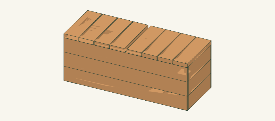
Build a 46.5-inch cedar storage bench with corner posts, a slatted draining floor and two lift-off seat panels that come off without hinges or lid stays.
01 / See the shape
View the project
Loading the 3D view…
Drag to turn. Pinch or use + / − to zoom. The written step covers workholding and tool use.

Scroll or swipe the enlarged drawing to read its dimensions. Choose Fit to see the whole drawing again.
Finished bench with both panels seated; inspect it with the panels lifted out.
02 / Plan your build
Before you start
Four 4 × 4 corner posts carry the seat. The 2 × 4 front, back and end rails sit directly on the post tops, so seat load bears wood on wood instead of hanging on screws. The cedar wall boards hang on the posts 0.5 in above the ground and tie the frame square. The seat is two separate lift-off panels. Battens under each panel drop 1.5 in inside the rails to locate it, so there is no hinge, lid stay or falling lid to trap fingers. The bench fails if a rail is screwed on without bearing fully on its posts, if the battens are fitted tight and swell against the rails, if the floor gaps clog and hold water, or if the box is used as a play space or latched shut. Seated use waits on a technical review of the 38-in rail span and the screwed wall joints.
Where it goes
Firm, level, free-draining paving, deck or compacted gravel where water does not pool. Do not place it on soft soil or lawn, on a slope, beside a drop or pool, or where children play unsupervised.
Footprint: 46.5 × 18 in for the bench. Allow about 30 in clear in front for lifting the panels and a dry, flat 24 × 20 in spot beside it to set a removed panel down
What to expect
Measure accurately, make square cuts in 4 × 4 stock, and drill and drive screws to marked layouts. Plan 9–11 hours over two days including layout and sanding, plus the finish drying time on the product label.
A planning estimate for the hands-on work, once the materials are bought and the tools are set up. It has not been timed on a finished build.
Check the spot
- Firm, level, free-draining paving, deck or compacted gravel where water does not pool; not soft soil, lawn, a slope, beside a drop or pool, or a place where children play unsupervised.
- A 46.5 × 18 in area plus 30 in clear in front and a dry 24 × 20 in spot for a removed panel.
- A flat bench or floor large enough to lay out a 46.5 in wall and clamp it without reaching across a moving blade.
Stop and check first if…
- Stop if a rail does not bear fully on its post tops, a board splits at a screw, a screw strips, or the box rocks. Unload and correct it before continuing.
- Stop if the measured stock differs from the parts table. Rework the cut lengths and screw lengths before cutting.
- Stop using the box and remove its contents if a child has been inside it or tries to climb in. Do not latch, lock or weight the panels.
- Do not change the length, depth, rail size or seat board size without recalculating every part and connection.
Work safely
- Support the 4 × 4 on both sides of the cut and clamp it. Never hold a short post offcut by hand beside the blade.
- Clamp boards before drilling, keep guards in place, and disconnect power before changing bits or blades.
- Carry the assembled box with two people by its bottom wall boards, not by a rail or a seat panel.
- Oily rags from a penetrating finish can heat up and catch fire as they dry. Lay them flat outdoors to dry, or seal them in a metal can filled with water, before disposal.
Budget
We have not put a price on this one yet. Lumber and hardware prices change by store and season, so price the list under What you need at your local supplier before you buy.
03 / Gather and cut
What you need
P — Corner post
4 pieces
Cedar 4 × 4; actual 3.5 × 3.5 in. One 4 × 4 × 8-ft board: 4 × 13.5 = 54 in, plus 4 kerfs of 0.125 in and 1 in end trim = 55.5 in of 96 in.
Both ends must be square because R and N bear on the top end. Reject a post with a split or check within 3 in of the top end.
F — Front and back wall board
6 pieces
Cedar 1 × 6; actual 0.75 × 5.5 in. Three 1 × 6 × 8-ft boards, two F per board: 2 × 46.5 = 93 in, plus 2 kerfs of 0.125 in and 1 in trim = 94.25 in of 96 in.
This layout leaves 1.75 in of spare length, so reject boards with end checks longer than 0.75 in. Mark the outside face and the bottom edge on each board.
E — End wall board
6 pieces
Cedar 1 × 6; actual 0.75 × 5.5 in. Shares three 1 × 6 × 8-ft boards with B. Board 4: five E (82.5 in + 5 kerfs 0.625 + 1 in trim = 84.1 in). Board 5: one E and four B (81.5 + 0.625 + 1 = 83.1 in). Board 6: two B, with the rest kept for a spare slat.
16.5 in equals the clear gap between the F inner faces. Check that gap on the standing walls before driving the end screws.
R — Front and back top rail
2 pieces
Cedar 2 × 4; actual 1.5 × 3.5 in, set on edge. One 2 × 4 × 8-ft board: 2 × 45 = 90 in, plus 2 kerfs of 0.125 in and 1 in trim = 91.25 in of 96 in.
Choose the straightest 2 × 4. Sight along the edge and reject one with more than 0.125 in crown, because R carries the seat across a 38-in clear span.
N — End top rail
2 pieces
Cedar 2 × 4; actual 1.5 × 3.5 in, set on edge. A second 2 × 4 × 8-ft board: 2 × 13.5 = 27 in, plus 2 kerfs and 1 in trim = 28.25 in. Keep the offcut.
13.5 in equals the clear gap between the R inner faces. Both ends must be square to bear on the post tops.
C — Floor cleat
2 pieces
Cedar 2 × 2; actual 1.5 × 1.5 in. One 2 × 2 × 8-ft board: 2 × 38 = 76 in, plus 2 kerfs of 0.125 in and 1 in trim = 77.25 in of 96 in.
38 in equals the clear gap between the post inner faces. Reject a cleat with a knot across its width.
B — Floor slat
6 pieces
Cedar 1 × 6; actual 0.75 × 5.5 in. Cut from 1 × 6 boards 5 and 6 as listed under E.
B is 0.25 in shorter than E. Label each stack separately so they are not swapped.
S — Seat board
8 pieces
Cedar 2 × 6; actual 1.5 × 5.5 in. Two 2 × 6 × 8-ft boards. Board 1: five S (90 in + 5 kerfs 0.625 + 1 in trim = 91.625 in). Board 2: three S (54 + 0.375 + 1 = 55.375 in).
Reject boards with loose knots or splits within 3 in of an end. Choose the seat face before cutting.
K — Seat panel batten
4 pieces
Cedar 2 × 2; actual 1.5 × 1.5 in. A second 2 × 2 × 8-ft board: 4 × 20.75 = 83 in, plus 4 kerfs of 0.125 in and 1 in trim = 84.5 in of 96 in.
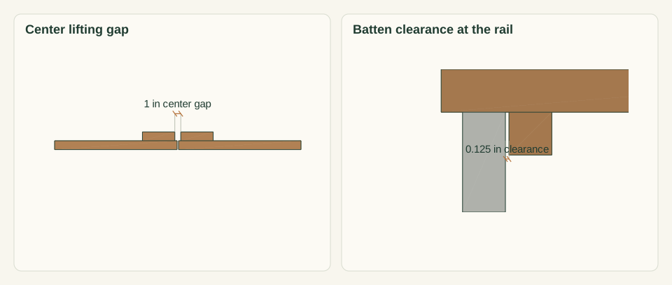
K sets the panel location and its clearance. Use straight, dry stock so the 0.125 in clearance to R and N holds.
Wall screws
78 items
#9 × 2 in stainless steel exterior wood or deck screw Buy at least 78 and keep spares separate from the installed count.
Drive from the outside face of F and E into P, R, N and C. Follow the screw maker's clearance, countersink and pilot instructions. No joint capacity is inferred.
Floor screws
24 items
#8 × 1.5 in stainless steel exterior wood screw Buy at least 24 and keep spares separate.
Four per B into C, giving 0.75 in of engagement in the 1.5 in cleat.
Seat batten screws
32 items
#9 × 2.5 in stainless steel exterior wood or deck screw Buy at least 32 and keep spares separate.
Drive up through K into S, giving 1 in of engagement and stopping 0.5 in below the seat face.
Exterior finish (optional)
1 item
Penetrating exterior wood finish whose label lists cedar Buy enough to cover all faces at the coverage stated on the label.
Optional. Apply it with the panels off the box and follow the label for drying time and rag disposal.
Cut list
| Piece | How many | Cut length | Note |
|---|---|---|---|
| P — Corner post | 4 | 13.5 × 3.5 × 3.5 in | Finished length × width × thickness; square ends unless the detail says otherwise. |
| F — Front and back wall board | 6 | 46.5 × 5.5 × 0.75 in | Finished length × width × thickness; square ends unless the detail says otherwise. |
| E — End wall board | 6 | 16.5 × 5.5 × 0.75 in | Finished length × width × thickness; square ends unless the detail says otherwise. |
| R — Front and back top rail | 2 | 45 × 3.5 × 1.5 in | Finished length × width × thickness; square ends unless the detail says otherwise. |
| N — End top rail | 2 | 13.5 × 3.5 × 1.5 in | Finished length × width × thickness; square ends unless the detail says otherwise. |
| C — Floor cleat | 2 | 38 × 1.5 × 1.5 in | Finished length × width × thickness; square ends unless the detail says otherwise. |
| B — Floor slat | 6 | 16.25 × 5.5 × 0.75 in | Finished length × width × thickness; square ends unless the detail says otherwise. |
| S — Seat board | 8 | 18 × 5.5 × 1.5 in | Finished length × width × thickness; square ends unless the detail says otherwise. |
| K — Seat panel batten | 4 | 20.75 × 1.5 × 1.5 in | Finished length × width × thickness; square ends unless the detail says otherwise. |
Tools
- Tape measure, combination square, framing square and sharp pencil
- 4-ft level and a straightedge
- Guarded miter saw or circular saw able to cut 3.5 in stock, with full support on both sides
- Drill/driver, countersink and bits matched to the chosen screws
- At least four clamps, 2 in support blocks, and 0.25, 0.625 and 0.75 in spacers
- Sanding block or random-orbit sander with 120-grit abrasive
Protective gear
- Eye protection during cutting, drilling and driving
- Hearing protection and a dust mask suited to cedar dust
- Closed footwear; keep loose clothing and gloves away from rotating blades and bits
04 / Put it together
Build steps
- 01
Confirm the site and use
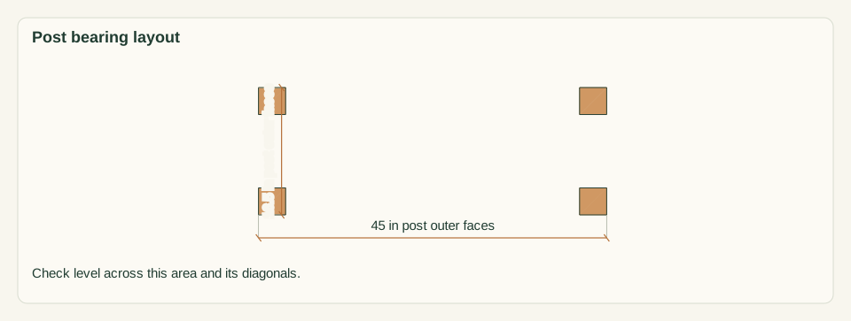
Choose a firm, level surface at least 46.5 × 18 in, with 30 in clear in front and a dry 24 × 20 in spot beside it for a removed panel. Lay a level across the area in both directions and along both diagonals. Keep the bench away from drops, pools and unsupervised play areas.
Close-up · Whole model shows the complete part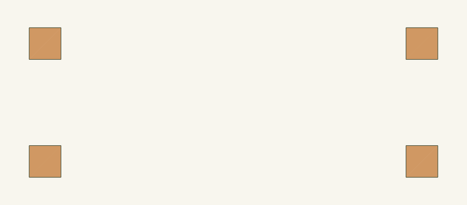
Loading the 3D view…
Drag to turn. Pinch or use + / − to zoom. The written step covers workholding and tool use.
Scroll or swipe the enlarged drawing to read its dimensions. Choose Fit to see the whole drawing again.
Planning reference only: the four post positions show where the bench bears on the ground.
Check: The surface is firm and drains, the level reads true in both directions, and no water stands where the four posts will bear.
- 02
Inspect and measure the stock
Measure every board at both ends and the middle. Required sections: 4 × 4 at 3.5 × 3.5 in, 2 × 4 at 1.5 × 3.5 in, 2 × 2 at 1.5 × 1.5 in, 2 × 6 at 1.5 × 5.5 in and 1 × 6 at 0.75 × 5.5 in. Reject boards with splits within 6 in of an end, loose knots, twist or more than 0.125 in bow.
Close-up · Whole model shows the complete part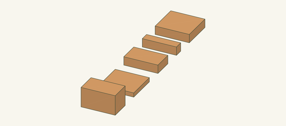
Loading the 3D view…
Drag to turn. Pinch or use + / − to zoom. The written step covers workholding and tool use.
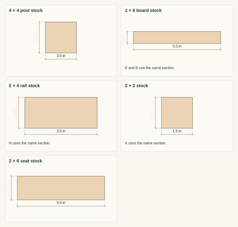
Scroll or swipe the enlarged drawing to read its dimensions. Choose Fit to see the whole drawing again.
Compare each measured section with the actual sizes these cuts depend on.
Check: Every section matches the parts table. If it does not, stop until the cut lengths and screw lengths are reworked for the stock you have.
- 03
Cut the posts, rails, cleats and battens
Square one end of each board before measuring. From the 4 × 4, cut four posts P at 13.5 in, supporting the board on both sides of the cut. From 2 × 4 board 1, cut two rails R at 45 in. From 2 × 4 board 2, cut two end rails N at 13.5 in. From 2 × 2 board 1, cut two floor cleats C at 38 in. From 2 × 2 board 2, cut four battens K at 20.75 in. Label every part.
Close-up · Whole model shows the complete part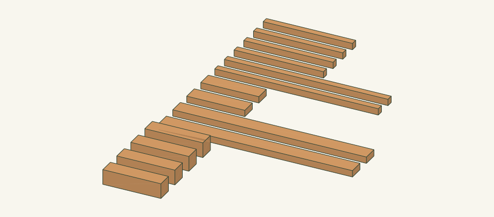
Loading the 3D view…
Drag to turn. Pinch or use + / − to zoom. The written step covers workholding and tool use.
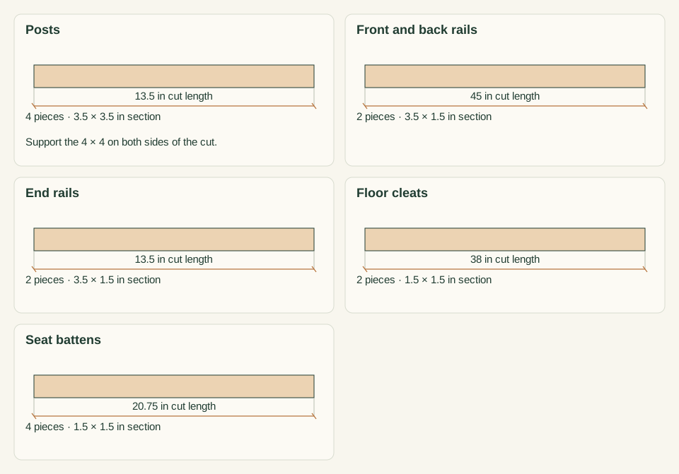
Scroll or swipe the enlarged drawing to read its dimensions. Choose Fit to see the whole drawing again.
The heavy frame parts are cut first, because the posts and rails set every other length.
Check: Like parts match within 0.0625 in and every cut end is square to both face and edge.
- 04
Cut the boards
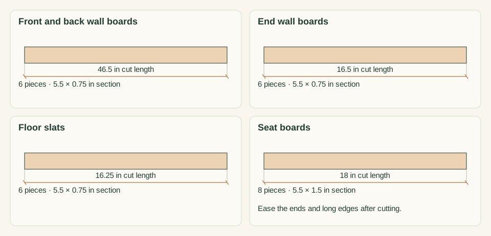
From three 1 × 6 boards, cut six wall boards F at 46.5 in, two per board. From the other three 1 × 6 boards, cut six end boards E at 16.5 in and six floor slats B at 16.25 in, and stack E and B separately. From the two 2 × 6 boards, cut eight seat boards S at 18 in. Ease the ends and long edges of S with a 0.125 in round-over or a sanding block.
Close-up · Whole model shows the complete part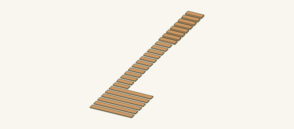
Loading the 3D view…
Drag to turn. Pinch or use + / − to zoom. The written step covers workholding and tool use.
Scroll or swipe the enlarged drawing to read its dimensions. Choose Fit to see the whole drawing again.
E and B differ by only 0.25 in, so they are cut and stacked separately.
Check: Six F, six E, six B and eight S are labeled, and each group matches within 0.0625 in.
- 05
Mark and drill the wall boards
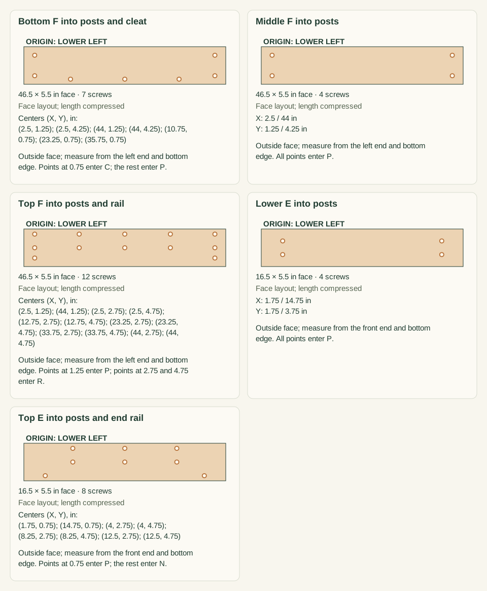
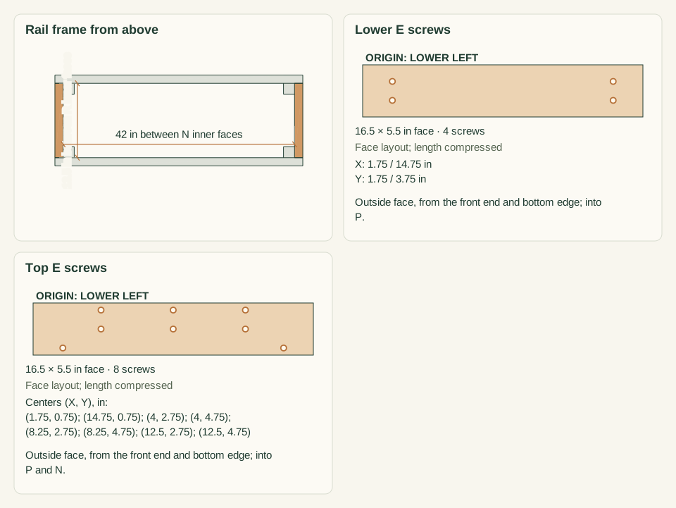
Lay each F and E outside face up. Measure x from the left end and height from the bottom edge. On two bottom F, mark x 2.5 and 44 at 1.25 and 4.25, plus x 10.75, 23.25 and 35.75 at 0.75. On two middle F, mark x 2.5 and 44 at 1.25 and 4.25. On two top F, mark x 2.5 and 44 at 1.25, plus x 2.5, 12.75, 23.25, 33.75 and 44 at 2.75 and 4.75. On four lower E, mark x 1.75 and 14.75 at 1.75 and 3.75. On two top E, mark x 1.75 and 14.75 at 0.75, plus x 4, 8.25 and 12.5 at 2.75 and 4.75. Drill clearance holes and countersinks to the screw maker's instructions.
Close-up · Whole model shows the complete part
Loading the 3D view…
Drag to turn. Pinch or use + / − to zoom. The written step covers workholding and tool use.
Scroll or swipe the enlarged drawing to read its dimensions. Choose Fit to see the whole drawing again.
Each board row has its own screw pattern, set by the post, rail or cleat behind it.
Check: There are 78 holes: 46 in F and 32 in E. Every hole is countersunk, and none is closer than 0.75 in to a board edge.
- 06
Build the front and back walls
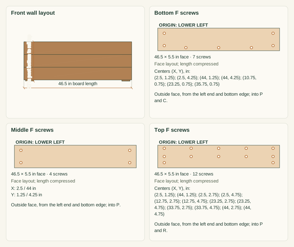
Lay two posts P on a flat bench, 38 in apart between inner faces. Butt rail R against the post top ends, its ends flush with the post outer faces. Set cleat C between the posts, 0.5 in up from the post bottoms. Put 2 in blocks under R and C so their outer faces sit level with the post faces. Lay the three F over the frame, outside face up. Each F end stands 0.75 in past the post outer face, and the bottom F edge sits 0.5 in above the post bottoms. Clamp, pilot into P, R and C, and drive 23 #9 × 2 in screws. Repeat for the back wall, for 46 screws in all.
Close-up · Whole model shows the complete part
Loading the 3D view…
Drag to turn. Pinch or use + / − to zoom. The written step covers workholding and tool use.
Scroll or swipe the enlarged drawing to read its dimensions. Choose Fit to see the whole drawing again.
Shown upright in final position; each wall is built flat on the bench with R bearing on the post ends.
Check: Each wall measures 17 in from post bottom to rail top, R bears fully on both post ends, and the board-face diagonals match within 0.125 in.
- 07
Join the end walls and end rails
With a helper, stand both walls upright on the flat surface, posts inward, 16.5 in apart between the F inner faces. Set each end rail N on the post tops between R0 and R1, its outer face flush with the rail ends. Clamp it there. Fit the three E boards at each end between the F ends, bottom edge 0.5 in above the post bottoms and top flush with N. Pilot and drive 32 #9 × 2 in screws: 4 into the posts on each lower E, and 2 into posts plus 6 into N on each top E.
Close-up · Whole model shows the complete part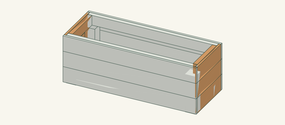
Loading the 3D view…
Drag to turn. Pinch or use + / − to zoom. The written step covers workholding and tool use.
Scroll or swipe the enlarged drawing to read its dimensions. Choose Fit to see the whole drawing again.
N bears on the post tops between the rails, then the E boards close each end.
Check: Both top diagonals read 49.86 in within 0.125 in, R and N are flush at 17 in, and the box does not rock on its four posts.
- 08
Fit the floor slats
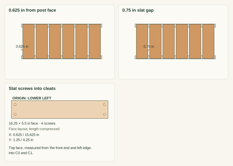
Lay the six floor slats B across cleats C. Set the first slat 0.625 in from the inner face of the left posts. Use 0.75 in spacers between slats, and stop each slat 0.125 in short of both F walls. Mark each slat 0.625 in from each end, at 1.25 and 4.25 in from its left edge. Pilot into C and drive 4 #8 × 1.5 in screws per slat, for 24 in all.
Close-up · Whole model shows the complete part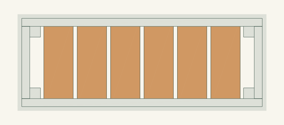
Loading the 3D view…
Drag to turn. Pinch or use + / − to zoom. The written step covers workholding and tool use.
Scroll or swipe the enlarged drawing to read its dimensions. Choose Fit to see the whole drawing again.
Even slat gaps let water drain and air move under stored items.
Check: The last slat ends 0.625 in from the right posts, all five gaps measure 0.75 in, and no screw point shows beneath the cleats.
- 09
Build the two seat panels
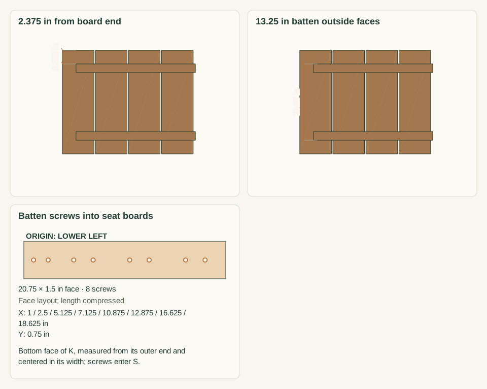
Lay four seat boards S face down on a flat bench with ends flush and 0.25 in spacers between them, giving a 22.75 × 18 in panel. Place two battens K so each sits 2.375 in in from a board end. Each batten starts 2.375 in from the outer long edge of the outer board and runs 0.375 in past the inner edge of the inner board. Mark each K from its outer end at 1, 2.5, 5.125, 7.125, 10.875, 12.875, 16.625 and 18.625 in, centered in its 1.5 in width. Clamp, pilot through K into S, and drive 16 #9 × 2.5 in screws. Build the second panel the same way and turn it end for end on the box.
Close-up · Whole model shows the complete part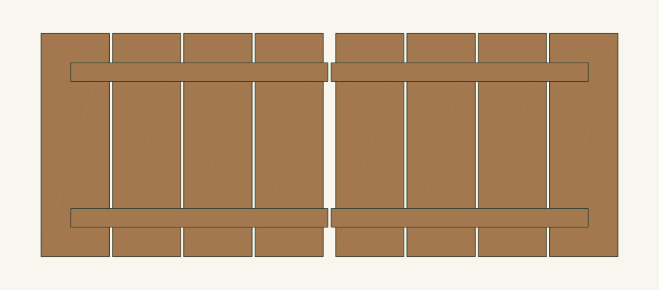
Loading the 3D view…
Drag to turn. Pinch or use + / − to zoom. The written step covers workholding and tool use.
Scroll or swipe the enlarged drawing to read its dimensions. Choose Fit to see the whole drawing again.
Panels shown alone from below; they are built face down on the bench, away from the box.
Check: The outside faces of each pair of battens measure 13.25 in apart, both battens are parallel, and no screw tip breaks the seat face.
- 10
Sand and finish the parts
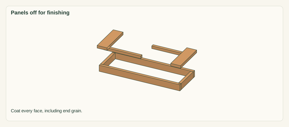
With both seat panels off the box, sand all exposed faces and edges of F, E, R, N, S and K to 120 grit and remove the dust. If you use the optional finish, coat every face, including the undersides of S, the battens K, the floor slats B and the end grain at the post bottoms. Let it dry for the full time on the label.
Close-up · Whole model shows the complete part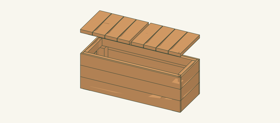
Loading the 3D view…
Drag to turn. Pinch or use + / − to zoom. The written step covers workholding and tool use.
Scroll or swipe the enlarged drawing to read its dimensions. Choose Fit to see the whole drawing again.
The panels are drawn raised 10 in to show they are finished off the box, with undersides and battens coated.
Check: The finish is dry to the label standard, all edges are eased, and no splinter or raised screw head remains.
- 11
Place the box and fit the panels
With two people, carry the box by its bottom wall boards to the checked site and set it on its four posts. Hold one panel at its outer end and at mid-depth under the inner edge. Lower it battens down so K drops inside R and N. Fit the second panel the same way. To remove a panel, lift it straight up at least 2 in to clear the battens, then set it flat on the ground.
Close-up · Whole model shows the complete part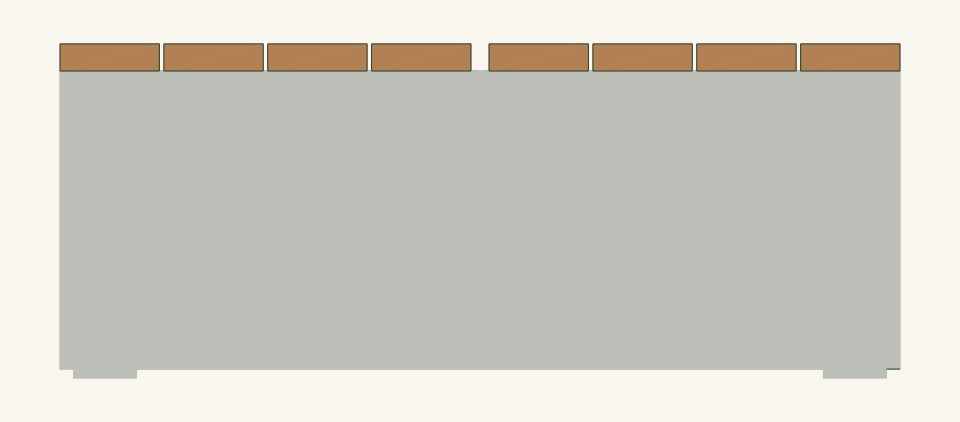
Loading the 3D view…
Drag to turn. Pinch or use + / − to zoom. The written step covers workholding and tool use.
Scroll or swipe the enlarged drawing to read its dimensions. Choose Fit to see the whole drawing again.
The panels lift straight up and out, with no hinge or stay, and the center gap is the hand hold.
Check: Both panels drop in and lift out without binding, the center gap measures between 0.75 and 1.25 in, and no fingers are under a panel edge that sits over a rail.
- 12
Inspect before first use
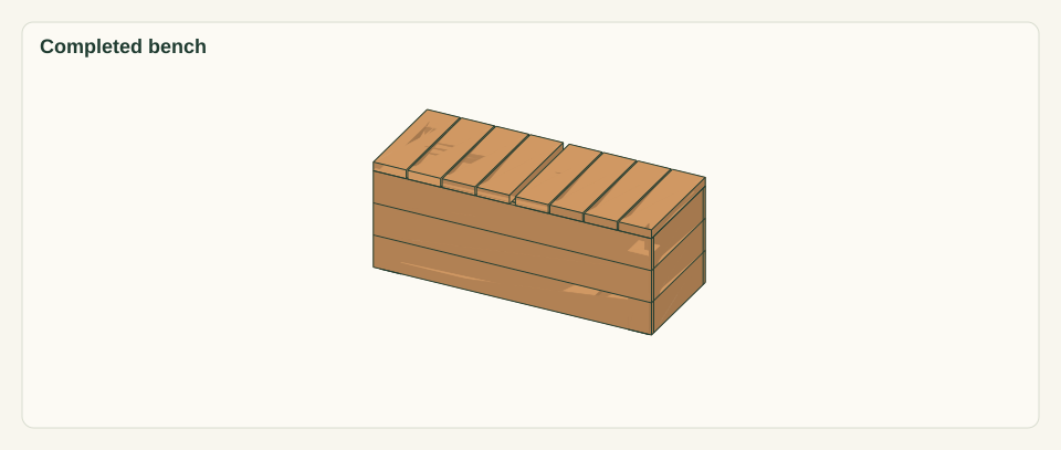
Count the 134 installed screws: 78 in the walls, 24 in the floor and 32 in the battens. Check that every head sits below the surface and that no tip shows inside the box. Confirm both R rest fully on the post tops and both N on their posts. Press down on each top corner of the box. Pour a cup of water on the floor and watch that it drains.
Close-up · Whole model shows the complete partLoading the 3D view…
Drag to turn. Pinch or use + / − to zoom. The written step covers workholding and tool use.
Scroll or swipe the enlarged drawing to read its dimensions. Choose Fit to see the whole drawing again.
Finished bench with both panels seated; inspect it with the panels lifted out.
Check: No rocking, split, joint gap, exposed tip or standing water is found. Record that seated use still waits on the review named in the limits.


05 / Keep it sound
Care
After the build
- Set the box on the checked site with all four posts bearing and no wedges. Lift each panel straight up and set it flat on the ground before reaching inside.
- Store light garden items that tolerate damp air. Keep the floor gaps clear, and do not store fuel, chemicals or sharp tools within a child's reach.
- Hold off seated use until the technical review named in the limits is recorded.
Check it each season
- Before each season and after storms, lift out both panels and check that R and N still bear on the post tops, that no screw has loosened or rusted, and that no board has split.
- Sweep debris out of the floor gaps and from around the battens. Recoat the finish when water no longer beads, with the panels off the box.
- Replace a split board or batten with a new part of the same cut size rather than adding a screw beside the crack.
If something looks wrong
- A panel binds as it drops in
- Lift it out and measure the gap between K and R or N. Sand or plane the batten face back to 0.125 in clearance; do not force the panel down.
- The box rocks on one post
- Move it to a level spot or regrade the surface. Check that the post has not loosened from its wall boards. Do not use loose wedges.
- Water stands on the floor
- Clear the slat gaps and the ground beneath them. If the site ponds, move the box to firmer, free-draining ground.
- A rail lifts off its post top or a wall joint opens
- Stop using the bench and empty it. Reclamp the rail onto the post, replace stripped screws and inspect for split boards.
- The center gap closes below 0.75 in
- Check the batten ends for damage or a loosened batten. Refit or replace K so the inner ends stop 0.25 in apart.
- A wall board splits at a screw
- Remove the board, cut a replacement to the same size, and pilot and countersink before driving.
Keep exploring