Garden storage · Guide 80
Build a Freestanding Long-Tool Stand
A wide-base stand with two separator rails and a removable boot tray for guarded tool ends.
01 / See the shape
View the project
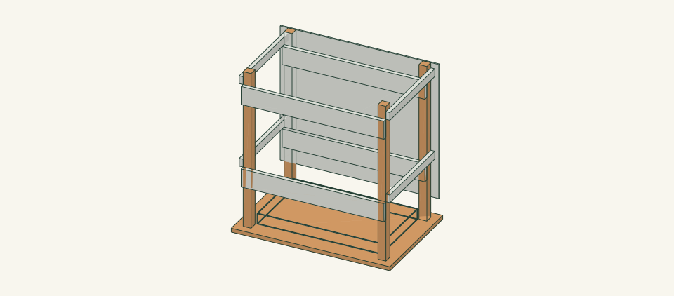
Loading the 3D view…
Drag to turn. Pinch or use + / − to zoom. The written step covers workholding and tool use.
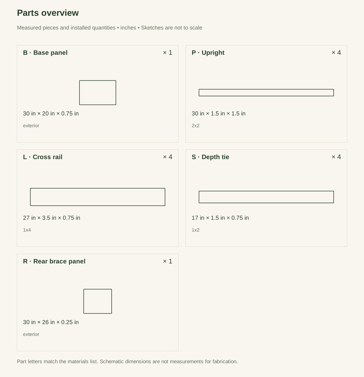
Scroll or swipe the enlarged drawing to read its dimensions. Choose Fit to see the whole drawing again.
Build a Freestanding Long-Tool Stand. Check the dimensions and build steps before cutting.
02 / Plan your build
Before you start
Two levels of cross rails and adjustable fabric separators keep a selected set of guarded long tools upright. Four overlapping depth ties join the sides, and a rear panel braces the frame. A broad base supports the tray. Store heavy guarded heads low and use a restrained rack instead if the chosen tool set can tip this stand.
Where it goes
A firm level indoor floor outside circulation routes; not a slope, stair landing or outdoor wind exposure.
Footprint: 30 × 20 in frame size; allow room around it to work and for anything that projects.
What to expect
Measure accurately, make supported square cuts and drill clamped joints. Plan 4–6 hours.
A planning estimate for the hands-on work, once the materials are bought and the tools are set up. It has not been timed on a finished build.
Check the spot
- A firm level indoor floor outside circulation routes; not a slope, stair landing or outdoor wind exposure.
- Measure the usable stock before marking. Keep the assembly area flat and large enough to clamp the work without reaching across a moving cutter.
Stop and check first if…
- Stop if a part splits, a fixing strips, or the assembled object rocks. Unload it before opening a joint.
- Do not substitute an unknown material section or make the object taller or wider without checking every affected part and joint.
Work safely
- Guard sharp tool heads before measuring or storing them, and keep heavy heads down on the tray. Do not leave a configuration that tips, shifts or catches a strap during removal. Use a properly restrained rack instead.
- Two people handle the empty frame while attaching the base. Unload all tools before moving or repairing it; keep straps short and the 30 × 20-inch base away from walking routes.
Budget
We have not put a price on this one yet. Lumber and hardware prices change by store and season, so price the list under What you need at your local supplier before you buy.
03 / Gather and cut
What you need
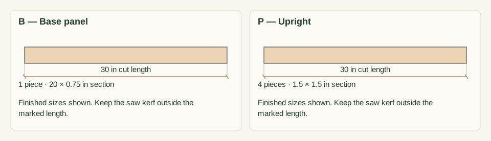
B — Base panel
1 piece
Exterior plywood, actual 0.75 in. Buy one 48 × 24 × 0.75-inch plywood panel and cut the 30 × 20-inch base with trim allowance.
Measure your boards before cutting. Build to the finished sizes written here, not the nominal lumber label.
P — Upright
4 pieces
Untreated surfaced 2 × 2, actual 1.5 square. Two 2 × 2 × 8-ft boards, two 30-inch cuts each.
Measure your boards before cutting. Build to the finished sizes written here, not the nominal lumber label.
L — Cross rail
4 pieces
Untreated surfaced 1 × 4, actual 0.75 × 3.5. Two 1 × 4 × 8-ft boards, two 27-inch cuts each.
Measure your boards before cutting. Build to the finished sizes written here, not the nominal lumber label.
S — Depth tie
4 pieces
Surfaced 1 × 2, actual 0.75 × 1.5. Buy one nominal 1 × 2 × 8-ft board, actual 0.75 × 1.5 in; cut four 17-inch ties.
Measure your boards before cutting. Build to the finished sizes written here, not the nominal lumber label.
R — Rear brace panel
1 piece
Exterior plywood, actual 0.25 in. Buy one 48 × 48 × 0.25-inch plywood panel; cut the 30 × 26-inch back.
Measure your boards before cutting. Build to the finished sizes written here, not the nominal lumber label.
T — Removable drip tray
1 piece
Clean plastic tray at most 23.5 × 13.5 × 2 inches INCLUDING its rim; remove through the open front below the first rail. One selected tray measured before fitting.
Tray is not a lifting handle or a structural brace.
Rail screws
32 items
#8 × 1.5-in exterior wood screws Purchase at least 32; keep spare hardware separate from the installed count.
Use one consistent product and follow its pilot and driving instructions.
Base screws
8 items
#8 × 2.25-in exterior wood screws Purchase at least 8; keep spare hardware separate from the installed count.
Use one consistent product and follow its pilot and driving instructions.
Brace screws
16 items
#6 × 1-in exterior screws Purchase at least 16; keep spare hardware separate from the installed count.
Use one consistent product and follow its pilot and driving instructions.
Tool separation loops
4 items
Adjustable reusable fabric straps, fitted around rail pairs without loose tails Buy four broad reusable straps long enough to loop around both upper rails, at least 40 inches each including buckle adjustment.
Loop locations depend on guarded tool dimensions; straps are separators, not fall-arrest or rated lifting straps.
Cut list
| Piece | How many | Cut length | Note |
|---|---|---|---|
| B — Base panel | 1 | 30 × 20 × 0.75 in | Finished length × width × thickness; square ends unless the detail says otherwise. |
| P — Upright | 4 | 30 × 1.5 × 1.5 in | Finished length × width × thickness; square ends unless the detail says otherwise. |
| L — Cross rail | 4 | 27 × 3.5 × 0.75 in | Finished length × width × thickness; square ends unless the detail says otherwise. |
| S — Depth tie | 4 | 17 × 1.5 × 0.75 in | Finished length × width × thickness; square ends unless the detail says otherwise. |
| R — Rear brace panel | 1 | 30 × 26 × 0.25 in | Finished length × width × thickness; square ends unless the detail says otherwise. |
Tools
- Tape or rule, square and sharp pencil
- Clamps, a flat bench and sacrificial backing
- Suitable guarded saw for the specified stock
- Drill/driver, depth stop and bits matched to the chosen screws
- Fine abrasive and a dust brush
Protective gear
- Eye protection during cutting and drilling
- Hearing protection and dust collection appropriate to the actual tools
- Closed footwear; keep loose clothing and gloves away from rotating cutters
04 / Put it together
Build steps
- 01
Measure the guarded tool set
Lay out up to four intended long tools with their blade guards fitted. Check their head widths, lengths and likely balance. Reject a configuration whose heavy heads must be stored high above the base.
Close-up · Whole model shows the complete part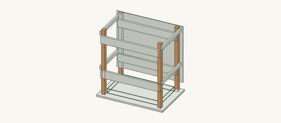
Loading the 3D view…
Drag to turn. Pinch or use + / − to zoom. The written step covers workholding and tool use.
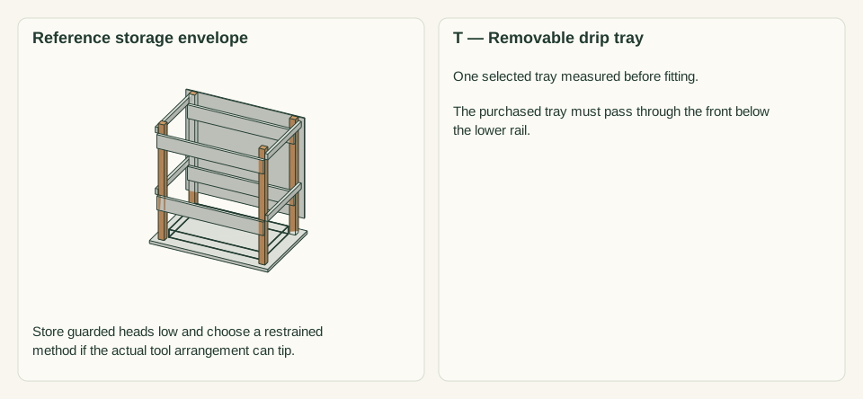
Scroll or swipe the enlarged drawing to read its dimensions. Choose Fit to see the whole drawing again.
Check the actual guarded tool set and broad base before cutting. No tool weight or anti-tip rating is demonstrated by the model.
Check: All tools can rest guarded end down in the selected tray.
- 02
Cut the base and posts
Cut the 30 × 20-inch base and four 30-inch posts. Mark the front post lower-left corners at(1.5, 1.5) and(27, 1.5), and rear corners at(1.5, 17) and(27, 17), measured from the BASE front-left. Post outside rear faces are 18.5 inches from the front, leaving 1.5 inches of base behind them.
Close-up · Whole model shows the complete part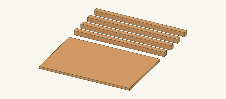
Loading the 3D view…
Drag to turn. Pinch or use + / − to zoom. The written step covers workholding and tool use.
Scroll or swipe the enlarged drawing to read its dimensions. Choose Fit to see the whole drawing again.
Cut the base and four matching posts first. Preserve the labeled base corner for every placement measurement.
Check: Four post footprints fit the base and leave the full broad footprint intact.
- 03
Mark the two rail levels
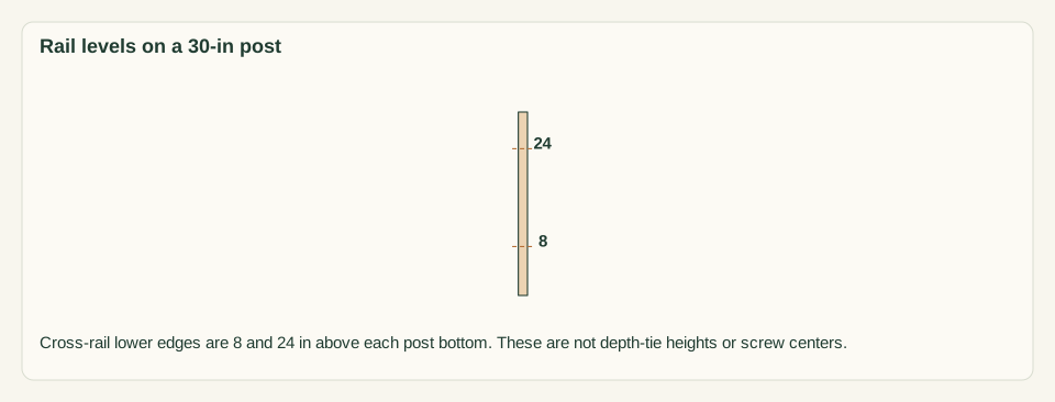
From the base top, mark cross-rail lower edges 8 and 24 inches up each post. Label front/back faces and keep every measurement from the same bottom starting edge.
Close-up · Whole model shows the complete part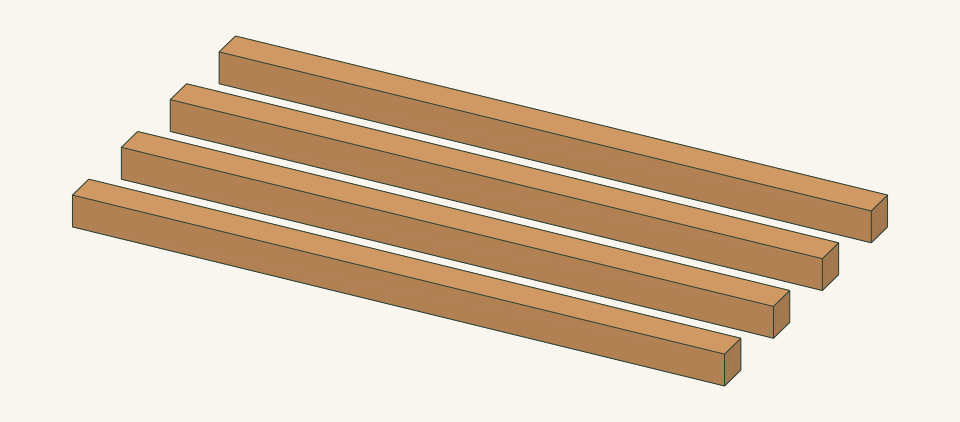
Loading the 3D view…
Drag to turn. Pinch or use + / − to zoom. The written step covers workholding and tool use.
Scroll or swipe the enlarged drawing to read its dimensions. Choose Fit to see the whole drawing again.
Mark both cross-rail lower edges from the post bottoms before building the two faces.
Check: Corresponding rail marks match across all four posts.
- 04
Make the two cross-rail faces
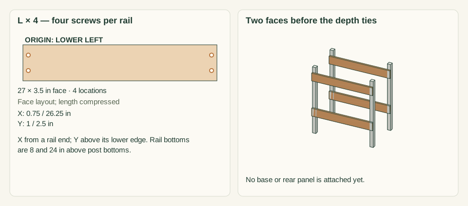
Cut four 27-inch rails. Clamp two across the FRONT faces of each post pair, with ends flush to the outer post sides. Lower edges are 8 and 24 inches above the post bottoms. On each rail mark columns 0.75 inch from its ends and holes 1 and 2.5 inches above its bottom. Drill clearances through rails and pilots into posts; install 16 #8 × 1.5-inch screws.
Close-up · Whole model shows the complete part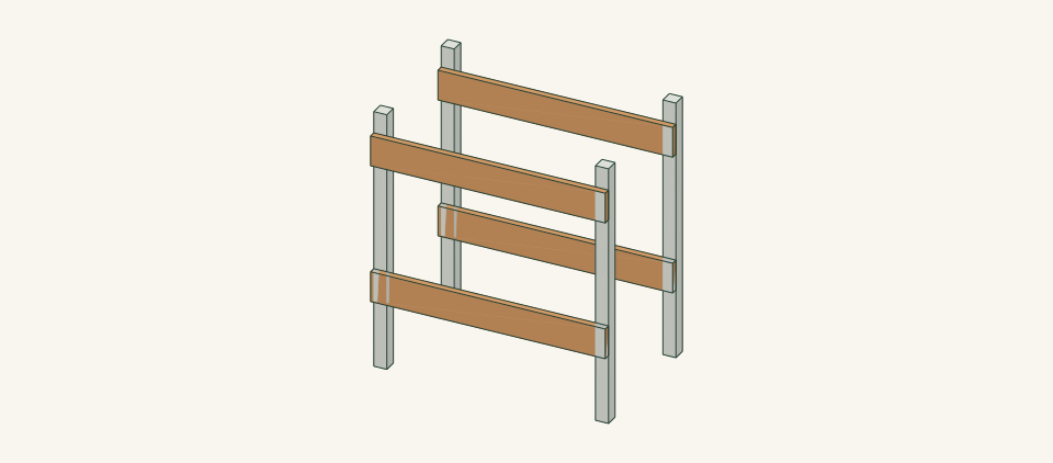
Loading the 3D view…
Drag to turn. Pinch or use + / − to zoom. The written step covers workholding and tool use.
Scroll or swipe the enlarged drawing to read its dimensions. Choose Fit to see the whole drawing again.
Build the matching front and rear cross-rail faces. Both rail pairs attach to the front faces of their posts.
Check: Front and rear assemblies match, with two screws into every post overlap.
- 05
Lap depth ties across the posts
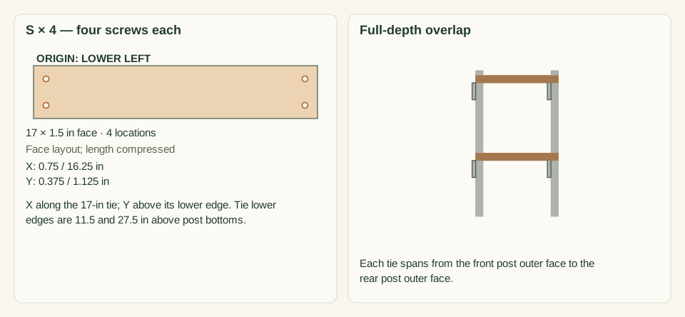
Cut four 17-inch ties. Fit them on the OUTSIDE left and right post faces, spanning the full front-to-rear post length from y 1.5 to 18.5. Their lower edges are 11.5 and 27.5 inches above the post bottoms. Each end overlaps a post 1.5 inches. Mark holes 0.75 inch from each tie end, heights 0.375/1.125 above its bottom. Install 16 #8 × 1.5-inch screws after clamped pilots.
Close-up · Whole model shows the complete part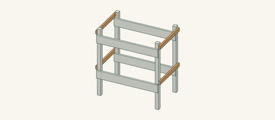
Loading the 3D view…
Drag to turn. Pinch or use + / − to zoom. The written step covers workholding and tool use.
Scroll or swipe the enlarged drawing to read its dimensions. Choose Fit to see the whole drawing again.
Lap each depth tie across the outside post faces. Both ends overlap solid posts rather than butting into open space.
Check: All eight tie ends overlap solid posts; the ties do not butt into unsupported end joints.
- 06
Fasten the base to the post ends
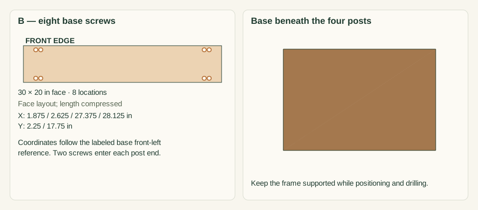
With help, invert the empty frame and clamp the base at its marked post footprints. From the BASE front-left mark x 1.875/2.625 and 27.375/28.125, each at y 2.25 and 17.75. Drill clearances through the base and pilots into post ends. Fit eight #8 × 2.25-inch screws flush and return the stand upright.
Close-up · Whole model shows the complete part
Loading the 3D view…
Drag to turn. Pinch or use + / − to zoom. The written step covers workholding and tool use.
Scroll or swipe the enlarged drawing to read its dimensions. Choose Fit to see the whole drawing again.
With help, invert the empty frame and fasten upward through the base into the four post ends.
Check: The base is flat, with two screws per post and no exposed underside heads.
- 07
Screw the rear panel to posts only
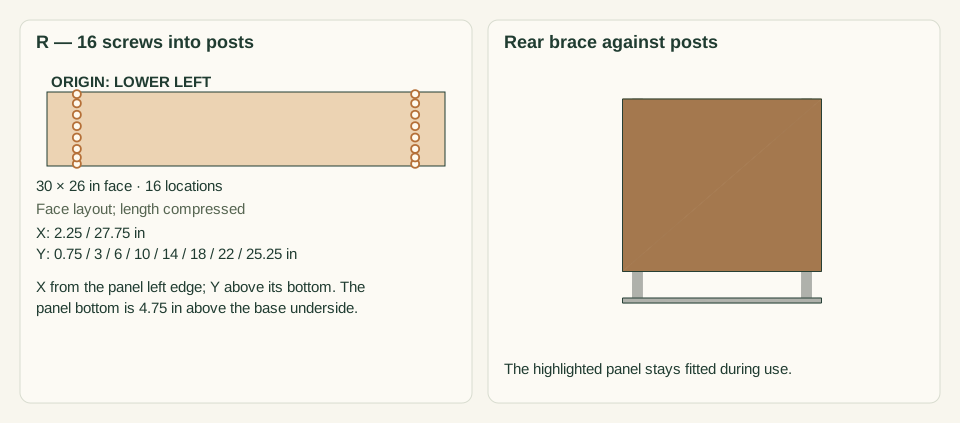
Cut the 30 × 26-inch rear panel from 0.25-inch plywood. Set the 30 × 26-inch rear panel against the REAR post faces with its bottom 4.75 inches above the base underside. Mark columns 2.25 and 27.75 from its left edge. At each mark heights 0.75, 3, 6, 10, 14, 18, 22 and 25.25 above the PANEL bottom. Drill and fit 16 #6 × 1-inch screws into posts only. The rear cross rails are on the other side of those posts.
Close-up · Whole model shows the complete part
Loading the 3D view…
Drag to turn. Pinch or use + / − to zoom. The written step covers workholding and tool use.
Scroll or swipe the enlarged drawing to read its dimensions. Choose Fit to see the whole drawing again.
Fit the rear panel directly against the rear posts. Its screws do not bridge the gap to the inset cross rails.
Check: Every back screw enters a post; none spans the gap to a rear cross rail.
- 08
Fit the smaller tray and separators
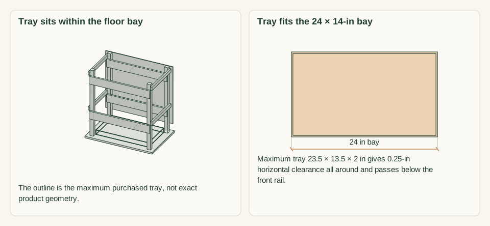
Slide the clean tray through the front under the lower rail. Maximum outside size including rim is 23.5 × 13.5 × 2 inches; center it with 0.25-inch clearance around the 24 × 14-inch floor bay. Fit four adjustable fabric separator loops around the upper front/rear rails, starting at x 6, 12, 18 and 24 from the base left edge. Adjust to the guarded shafts and secure loose tails.
Close-up · Whole model shows the complete part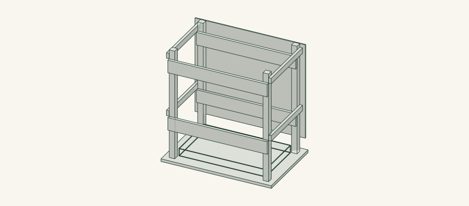
Loading the 3D view…
Drag to turn. Pinch or use + / − to zoom. The written step covers workholding and tool use.
Scroll or swipe the enlarged drawing to read its dimensions. Choose Fit to see the whole drawing again.
Slide in the smaller tray and fit adjustable separation loops. The loops separate tools; they are not restraints.
Check: Tray slides out without tilting and each intended tool can be removed without catching a loop.
- 09
Test the empty insertion sequence
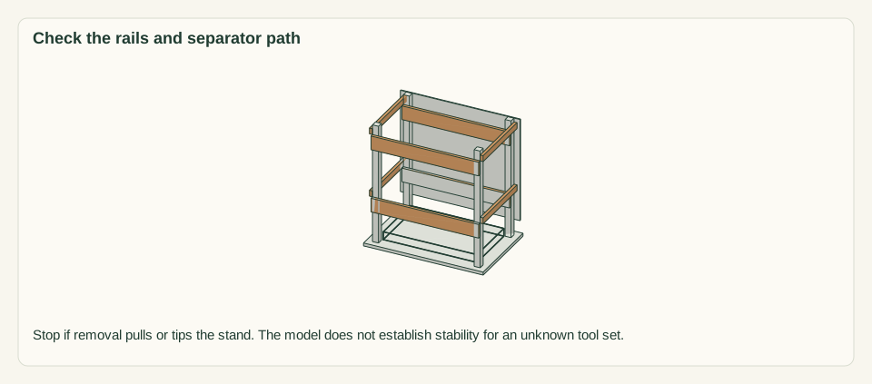
With another adult controlling the stand, insert and remove one guarded empty/light tool at a time. Watch whether lifting a tool pulls the stand or catches a strap. Stop for any tendency to tip.
Close-up · Whole model shows the complete part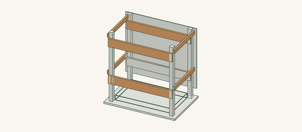
Loading the 3D view…
Drag to turn. Pinch or use + / − to zoom. The written step covers workholding and tool use.
Scroll or swipe the enlarged drawing to read its dimensions. Choose Fit to see the whole drawing again.
Trial insertion and removal of one actual guarded tool while a second person controls the stand.
Check: Tool removal is controlled and does not lift or shift the base.
- 10
Store the permitted set and inspect
Use only the tool set that fits stably, keeping heavy heads low. Unload before relocating or repairing. Where the actual tools make the stand unstable, use a properly restrained storage method instead.
Close-up · Whole model shows the complete partLoading the 3D view…
Drag to turn. Pinch or use + / − to zoom. The written step covers workholding and tool use.
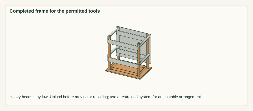
Scroll or swipe the enlarged drawing to read its dimensions. Choose Fit to see the whole drawing again.
Keep the broad base clear of walking routes and inspect the unloaded frame and tray before reuse.
Check: The stand is outside walking routes and no unstable configuration is retained.


05 / Keep it sound
Care
After the build
- The broad base does not provide a universal anti-tip rating. Reject tools or arrangements that move the stand during insertion or removal.
- Empty the tray to prevent standing water and corrosion around guarded tool heads.
Check it each season
- Inspect connections and hand-contact edges before use. Unload before tightening or replacing parts; replace a cracked member rather than adding a screw beside the crack.
- Brush off debris, wipe only as needed and dry with air around the joints. Store dry when the item is not in use.
If something looks wrong
- Stand tips as a tool is removed
- Unload it and use an appropriate restrained rack; do not add a top weight.
- A shaft snags a loop
- Adjust or replace the loop around the guarded tool; keep hands out of the closing gap.
- Base edge lifts
- Inspect floor flatness, panel warp and frame squareness before use.
- Tray stays wet
- Remove and dry it, inspect the base and change storage practice rather than leaving water under tools.
Keep exploring