Garden benches · Guide 45
Build an L-Shaped Corner Garden Bench from Two Bolted Runs
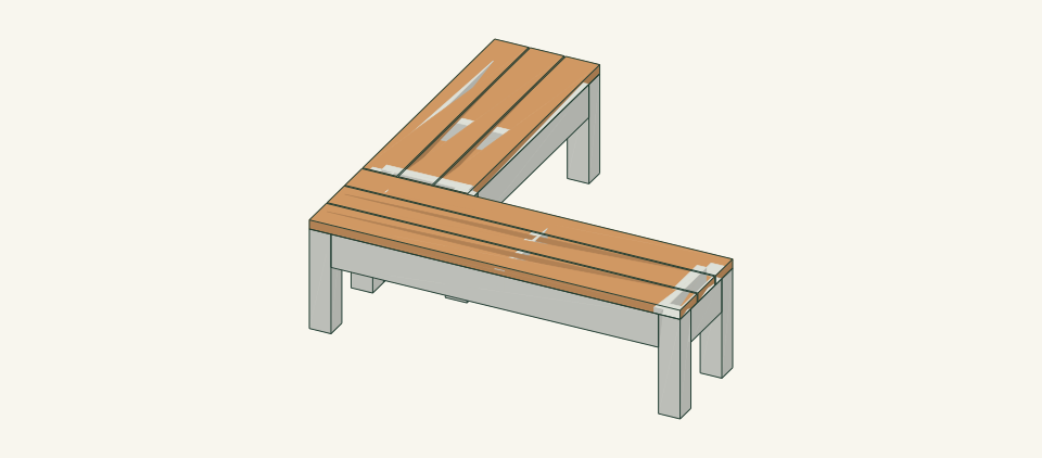
Build a backless cedar corner bench from two complete four-legged seat runs joined by two inspectable through-bolts, forming a 60 × 60-inch L for a garden corner.
01 / See the shape
View the project
Loading the 3D view…
Drag to turn. Pinch or use + / − to zoom. The written step covers workholding and tool use.

Scroll or swipe the enlarged drawing to read its dimensions. Choose Fit to see the whole drawing again.
Press the five outer seat corners and the corner joint in turn.
02 / Plan your build
Before you start
Each run is a complete bench on its own four legs. Run A is 60 × 17 in and run B is 43 × 17 in. Run B butts against the back apron of run A to form the L. No leg, rail or slat is shared across the corner, so neither run depends on the other for support. Two through-bolts pass through the face grain of the two touching aprons. They hold the runs in line and can be inspected and tightened from under the seat. The slats end flush with the leg faces, so no seat area sits outside the leg line. The bench can fail in four main ways. The pocket-screw joints can be driven out of square, or they can loosen and let a run rack. Slat screws can split the slats or cleats. A run can be set on soft or uneven ground so that a leg stops bearing. The corner bolts can be wrongly used to hold up a run that rocks on its own.
Where it goes
Firm, level paving or compacted gravel at least 60 × 60 in, with 30 in clear in front of each seat run. Do not place it on soft soil, a slope, a deck of unknown capacity, or near a drop or retaining-wall edge.
Footprint: An L of two 17-in-deep arms inside a 60 × 60 in square, each arm 60 in long from the outside corner. Allow 30 in clear in front of each seat run and 24 in at the free ends for assembly access
What to expect
Measure accurately, make supported square cuts, drill pocket holes and assemble clamped frames square. Plan 12–14 hours over two days for two people, plus the finish drying time on the product label.
A planning estimate for the hands-on work, once the materials are bought and the tools are set up. It has not been timed on a finished build.
Check the spot
- Confirm firm, level paving or compacted gravel at least 60 × 60 in, with 30 in clear in front of each seat run, and no drop or slope edge within reach.
- Confirm a flat assembly area at least 8 × 8 ft where each run can be clamped without reaching across a moving cutter.
Stop and check first if…
- Stop if a part splits, a pocket screw strips, a screw tip breaks an outer face, or a run rocks on its own. Unload the bench before opening a joint.
- Stop if a pocket recess comes within 0.5 in of a corner bolt washer, or if the corner holes do not align with both runs bearing. Refer the corner layout for review rather than enlarging or moving the holes by eye.
- Do not lengthen either run, change the stock section or add a back without reworking the parts, spans and connections and reopening review.
Work safely
- Support 4 × 4 and 10-ft stock fully on both sides of the cut and clamp it. Never hold a short offcut by hand beside the blade.
- Clamp each piece in the pocket-hole jig before drilling, clamp the stacked corner aprons to backing before boring, and keep fingers clear of both bits.
- Follow the saw, drill and finish manufacturer instructions. Keep guards in place and disconnect power before changing a blade or bit.
- Lift each run with two people by its aprons, never by a slat end. Oily finish rags can heat and ignite; dry them flat outdoors or seal them in a water-filled metal can.
Budget
We have not put a price on this one yet. Lumber and hardware prices change by store and season, so price the list under What you need at your local supplier before you buy.
03 / Gather and cut
What you need
L — Leg
8 pieces
Cedar 4 × 4, actual 3.5 × 3.5 in. Two 4 × 4 × 8-ft posts. Each post yields 5 legs: 5 × 16.5 + 5 × 0.125 kerf + 1 trim = 84.125 in of 96. Two posts give 10 legs and 8 are needed.
Measure the actual section at both ends. Reject posts with end checks within 6 in of a cut. Mark the top end of every leg.
RL — Long side apron (run A)
2 pieces
Cedar 2 × 6, actual 1.5 × 5.5 in. One from each of 2 × 6 × 10-ft boards 1 and 2. Each board holds one SL and one RL: 60 + 53 + 2 × 0.125 + 1 trim = 114.25 in of 120.
The corner apron RA1 receives the bolt holes. Choose a straight board with no knots in the first 12 in of its corner end.
RS — Short side apron (run B)
2 pieces
Cedar 2 × 6, actual 1.5 × 5.5 in. One from board 3, cut with one SL and two E. One from 2 × 6 × 8-ft board 5: 42.75 + 36 + 2 × 0.125 + 1 trim = 80 in of 96.
Check the length against the 43 in run B frame: 43 − 2 × 3.5 = 36.
E — End apron
4 pieces
Cedar 2 × 6, actual 1.5 × 5.5 in. Two from board 3: 60 + 36 + 10 + 10 + 4 × 0.125 + 1 trim = 117.5 in of 120. Two from board 4.
EB0 is the corner apron and receives the bolt holes. Choose a clear piece with no knot near its middle.
C — Slat cleat
6 pieces
Cedar 2 × 4, actual 1.5 × 3.5 in. One 2 × 4 × 8-ft board: 6 × 14 + 6 × 0.125 + 1 trim = 85.75 in of 96.
The slat screws land in the 1.5 in top edge. Reject pieces with cracks or knots in that edge.
SL — Long seat slat (run A)
3 pieces
Cedar 2 × 6, actual 1.5 × 5.5 in. One from each of 2 × 6 × 10-ft boards 1, 2 and 3. Cut it first, from a squared end.
Pick the best face for the seat. Reject splits within 6 in of an end or more than 0.125 in cup.
SS — Short seat slat (run B)
3 pieces
Cedar 2 × 6, actual 1.5 × 5.5 in. Two from 2 × 6 × 10-ft board 4: 2 × 42.75 + 2 × 10 + 4 × 0.125 + 1 trim = 107 in of 120. One from board 5. In total buy four 2 × 6 × 10-ft boards and one 2 × 6 × 8-ft board. Buy one extra 8-ft board if defects are likely.
The slat is 0.25 in shorter than the 43 in frame. This leaves the corner gap against run A.
Pocket-hole screws
56 items
2.5 in coarse-thread pocket-hole screws for 1.5 in stock, exterior coating compatible with cedar Purchase at least 56; keep spares separate from the installed count.
16 in RL and RS, 16 in E, 24 in C. Follow the jig maker's screw and clutch guidance. Confirm that no tip breaks an outer apron face. No connection capacity is inferred.
Seat slat screws
36 items
#10 × 3 in exterior wood screws, Type 305 stainless or exterior-coated and rated for cedar Purchase at least 36; keep spares separate from the installed count.
6 slats × 3 cleats × 2 = 36. Drill a clearance hole through the slat and a pilot into C as the screw maker directs. Countersink just below the seat face.
Corner bolts
2 items
5/16 × 4 in hex-head bolts, Type 304 stainless or hot-dip galvanized Buy 2.
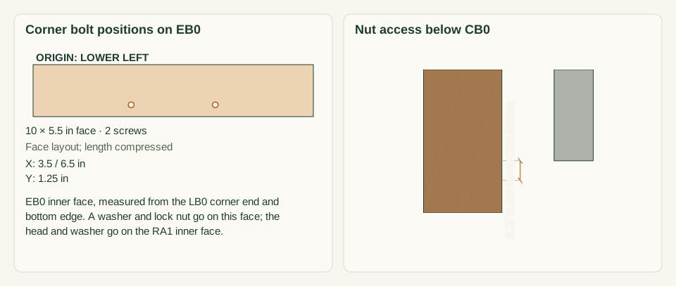
Fit them through EB0 and RA1 in 11/32 in holes, 3.5 and 6.5 in from the corner ends and 1.25 in above the apron bottoms. Insert each bolt from the RA1 side.
Corner washers
4 items
5/16 in flat washers, same material as the bolts Buy 4.
Fit one under each bolt head on the RA1 inner face and one under each nut on the EB0 inner face.
Corner nuts
2 items
5/16 in nylon-insert lock nuts, same material as the bolts Buy 2.
Tighten until the washers seat firmly without crushing the wood. Do not mix stainless and galvanized parts on one bolt.
Cut list
| Piece | How many | Cut length | Note |
|---|---|---|---|
| L — Leg | 8 | 16.5 × 3.5 × 3.5 in | Finished length × width × thickness; square ends unless the detail says otherwise. |
| RL — Long side apron (run A) | 2 | 53 × 5.5 × 1.5 in | Finished length × width × thickness; square ends unless the detail says otherwise. |
| RS — Short side apron (run B) | 2 | 36 × 5.5 × 1.5 in | Finished length × width × thickness; square ends unless the detail says otherwise. |
| E — End apron | 4 | 10 × 5.5 × 1.5 in | Finished length × width × thickness; square ends unless the detail says otherwise. |
| C — Slat cleat | 6 | 14 × 3.5 × 1.5 in | Finished length × width × thickness; square ends unless the detail says otherwise. |
| SL — Long seat slat (run A) | 3 | 60 × 5.5 × 1.5 in | Finished length × width × thickness; square ends unless the detail says otherwise. |
| SS — Short seat slat (run B) | 3 | 42.75 × 5.5 × 1.5 in | Finished length × width × thickness; square ends unless the detail says otherwise. |
Tools
- Tape, combination square, 24 in level, straightedge and pencil
- Guarded miter saw or circular saw with a cutting guide and full board support
- Pocket-hole jig set for 1.5 in stock, with its stepped bit and collar
- Drill/driver with a drilling guide, countersink bit and 11/32 in drill bit at least 6 in long
- 1/2 in socket with extension and a 1/2 in box wrench
- Four bar clamps of at least 24 in and two of at least 36 in
- 0.25 in spacers, sacrificial backing board, sanding block, 120-grit abrasive and a dust brush
Protective gear
- Eye protection during cutting, drilling and sanding
- Hearing protection and dust collection or a dust mask suited to the actual tools
- Closed footwear; keep gloves and loose clothing away from rotating cutters
04 / Put it together
Build steps
- 01
Confirm the site and intended use
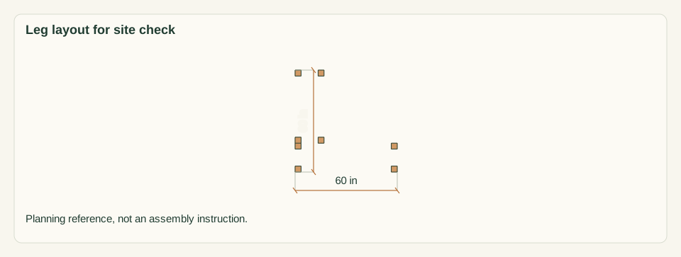
Choose firm, level paving or compacted gravel at least 60 × 60 in, with 30 in clear in front of each seat run. Lay a straightedge and level across the run A leg area, 60 × 17 in. Repeat across the run B leg area, 43 × 17 in, directly behind its left end. Check both directions.
Close-up · Whole model shows the complete part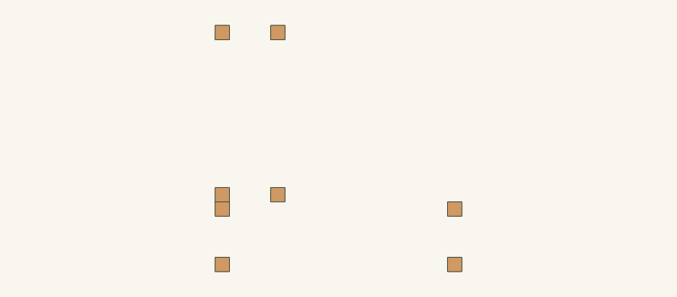
Loading the 3D view…
Drag to turn. Pinch or use + / − to zoom. The written step covers workholding and tool use.
Scroll or swipe the enlarged drawing to read its dimensions. Choose Fit to see the whole drawing again.
Planning reference only: the eight leg positions show where the base must be firm and level.
Check: The surface is firm and level across both areas. No soft soil, drop or slope edge lies under any leg.
- 02
Inspect and measure the stock
Measure every board at both ends and the middle. The 4 × 4 must be 3.5 × 3.5 in, the 2 × 6 boards 1.5 × 5.5 in and the 2 × 4 1.5 × 3.5 in. Reject boards with splits within 6 in of an end, loose knots, twist or more than 0.125 in bow. Number the 2 × 6 boards 1 to 5 as in the parts table.
Close-up · Whole model shows the complete part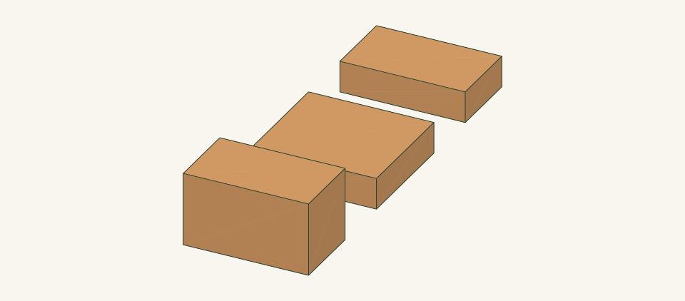
Loading the 3D view…
Drag to turn. Pinch or use + / − to zoom. The written step covers workholding and tool use.
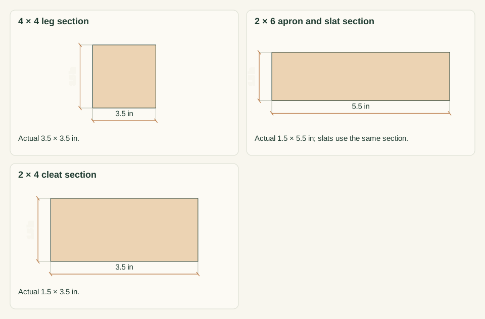
Scroll or swipe the enlarged drawing to read its dimensions. Choose Fit to see the whole drawing again.
Compare the measured sections with the three stock sizes before marking any cut.
Check: Every section matches the parts table, or work stops until the cuts are worked out again for the stock you have.
- 03
Cut the legs L and slat cleats C
Square one end of each board first. From the two 4 × 4 posts cut eight legs L at 16.5 in. From the 2 × 4 cut six cleats C at 14 in. Mark the top end of each leg and the top edge of each cleat. Chamfer the leg bottoms 0.25 in.
Close-up · Whole model shows the complete part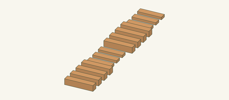
Loading the 3D view…
Drag to turn. Pinch or use + / − to zoom. The written step covers workholding and tool use.
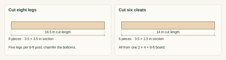
Scroll or swipe the enlarged drawing to read its dimensions. Choose Fit to see the whole drawing again.
Legs and cleats are cut and labeled before the long 2 × 6 work begins.
Check: All eight legs match within 0.0625 in. All six cleats match within 0.0625 in, and every end is square.
- 04
Cut the seat slats SL and SS
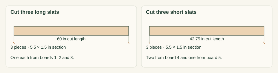
From a squared end of boards 1, 2 and 3 cut one SL at 60 in each. From board 4 cut two SS at 42.75 in. From board 5 cut one SS at 42.75 in. Mark the best face of each slat as the seat face. Ease the seat-face edges and ends with a 0.125 in round-over or sanding block.
Close-up · Whole model shows the complete part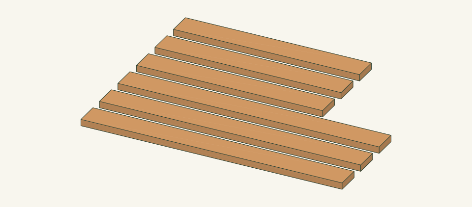
Loading the 3D view…
Drag to turn. Pinch or use + / − to zoom. The written step covers workholding and tool use.
Scroll or swipe the enlarged drawing to read its dimensions. Choose Fit to see the whole drawing again.
The longest pieces come first from each numbered 2 × 6 board.
Check: The slats lie flat face to face, like lengths match within 0.0625 in, and the seat faces have no splinters.
- 05
Cut the aprons RL, RS and E
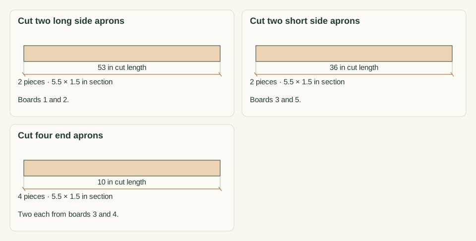
From the remainder of boards 1 and 2 cut one RL at 53 in each. From board 3 cut one RS at 36 in and two E at 10 in. From board 4 cut two E at 10 in. From board 5 cut one RS at 36 in. Mark the top edge and inside face of every apron. Label one RL as RA1 and one E as EB0, and mark one end of each as its corner end.
Close-up · Whole model shows the complete part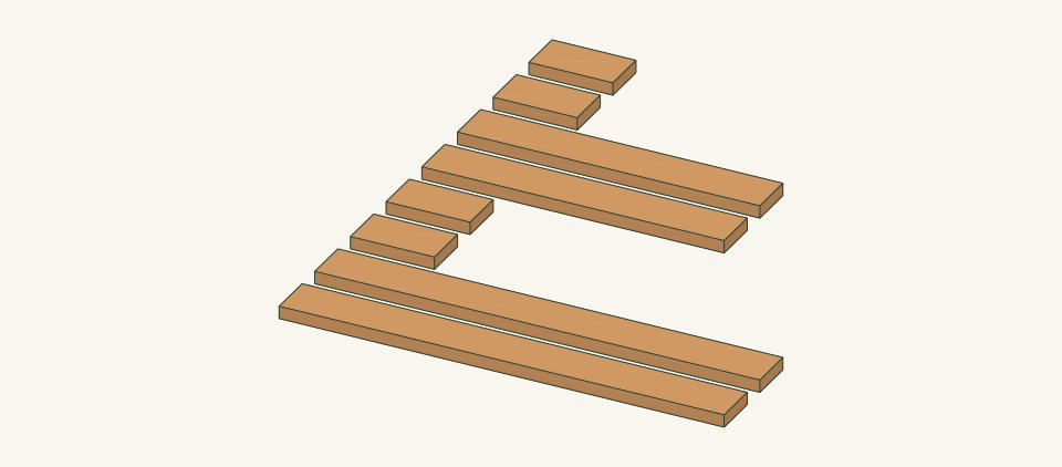
Loading the 3D view…
Drag to turn. Pinch or use + / − to zoom. The written step covers workholding and tool use.
Scroll or swipe the enlarged drawing to read its dimensions. Choose Fit to see the whole drawing again.
Aprons come from the board remainders; RA1 and EB0 are set aside as the corner pair with marked corner ends.
Check: Two RL, two RS and four E are cut and labeled. Paired lengths match within 0.0625 in, and both corner ends are marked.
- 06
Drill the 56 pocket holes
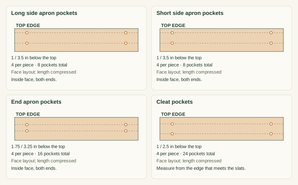
Set the jig and collar for 1.5 in stock as the jig instructions direct. On the inside face of each RL and RS, drill two holes at each end, 1.0 and 3.5 in below the top edge. On each E, drill two holes at each end, 1.75 and 3.25 in below the top edge. On each C, drill two holes at each end, 1.0 and 2.5 in below the top edge.
Close-up · Whole model shows the complete part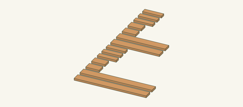
Loading the 3D view…
Drag to turn. Pinch or use + / − to zoom. The written step covers workholding and tool use.
Scroll or swipe the enlarged drawing to read its dimensions. Choose Fit to see the whole drawing again.
Different heights on side and end aprons keep the screws entering each leg apart.
Check: Count 56 holes, all on inside faces. No hole breaks through an outside face or the top edge.
- 07
Drill the two corner bolt holes
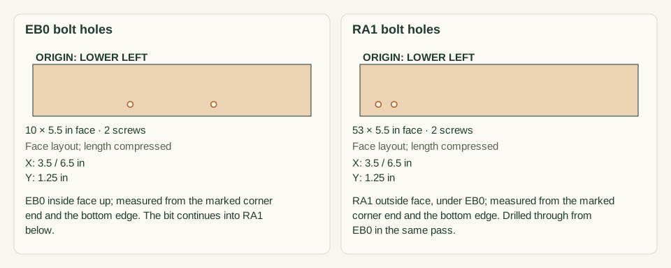
Lay RA1 inside face down on sacrificial backing. Set loose EB0 on it, outside face down, with the marked corner ends flush and the bottom edges flush, then clamp. On the EB0 inside face mark two points 3.5 and 6.5 in from the corner end and 1.25 in above the bottom edge. Drill 11/32 in holes square through EB0 and RA1.
Close-up · Whole model shows the complete part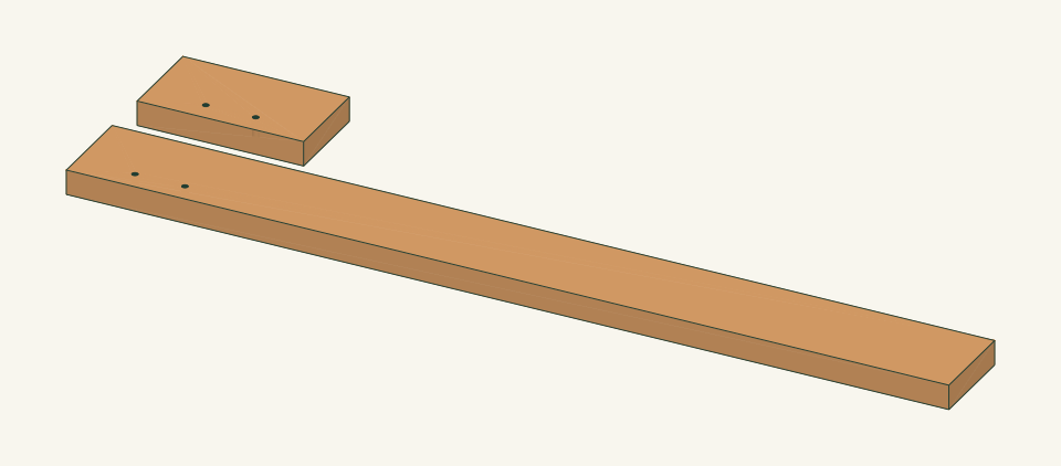
Loading the 3D view…
Drag to turn. Pinch or use + / − to zoom. The written step covers workholding and tool use.
Scroll or swipe the enlarged drawing to read its dimensions. Choose Fit to see the whole drawing again.
The two loose corner aprons are stacked outside face to outside face so one boring passes through both at matching points.
Check: Both holes pass straight through both aprons, and a bolt slides through each stacked pair without forcing.
- 08
Assemble the four end frames
Lay two legs L on a flat bench, 10 in apart between inner faces. Clamp one E between them with its top edge flush to the leg tops and its outer face flush to the leg faces. Its bottom edge sits 11 in above the leg bottoms. Drive 4 pocket screws. Build EA0, EA1, EB0 and EB1 frames this way, 16 screws in total. Set the EB0 corner end against the leg that becomes LB0.
Close-up · Whole model shows the complete part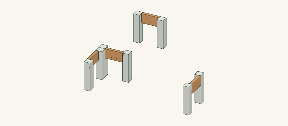
Loading the 3D view…
Drag to turn. Pinch or use + / − to zoom. The written step covers workholding and tool use.
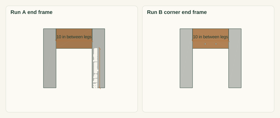
Scroll or swipe the enlarged drawing to read its dimensions. Choose Fit to see the whole drawing again.
Each end apron sits flush at the leg tops and outer faces, between two legs; the EB0 corner end goes against LB0.
Check: Each end frame is 17 in wide outside, E is square to both legs, and every top edge is flush.
- 09
Join the side aprons and square both runs
Stand the run A end frames 53 in apart between inner leg faces. Clamp RA0 and RA1 between the legs, tops flush and outer faces flush, holes facing in, with the RA1 corner end against leg LA2. Drive 8 screws. Repeat for run B with RB0 and RB1, 36 in between legs. Measure the top diagonals before removing clamps.
Close-up · Whole model shows the complete part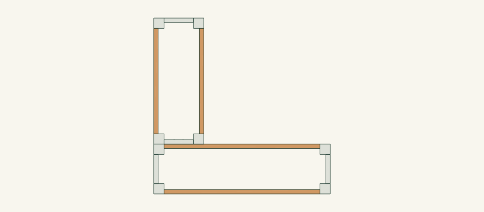
Loading the 3D view…
Drag to turn. Pinch or use + / − to zoom. The written step covers workholding and tool use.
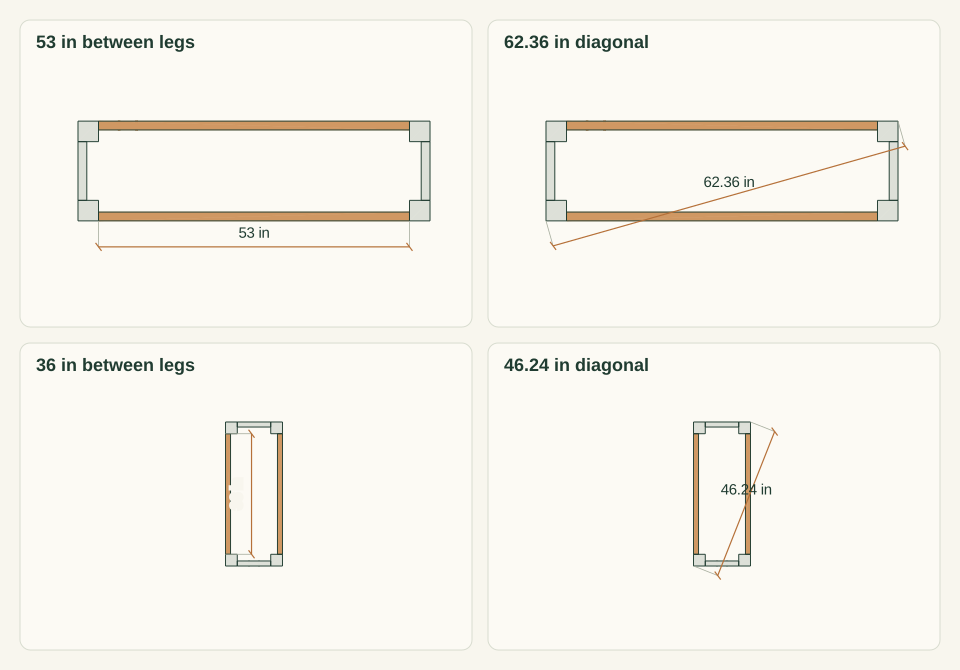
Scroll or swipe the enlarged drawing to read its dimensions. Choose Fit to see the whole drawing again.
Side aprons join the end frames into two separate rectangles, squared by diagonals.
Check: Run A diagonals read 62.36 in and run B diagonals read 46.24 in, each pair within 0.125 in, and no run rocks.
- 10
Fit the six slat cleats C
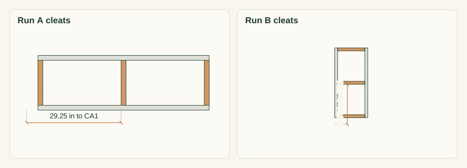
In run A, fit CA0 against the left legs, CA1 with its left face 29.25 in from the X 0 outer face, and CA2 against the right legs. In run B, fit CB0 against the front legs, CB1 with its near face 20.75 in from the Y 17 face, and CB2 against the back legs. Set every top flush with the apron tops and drive 4 screws each, 24 in total.
Close-up · Whole model shows the complete part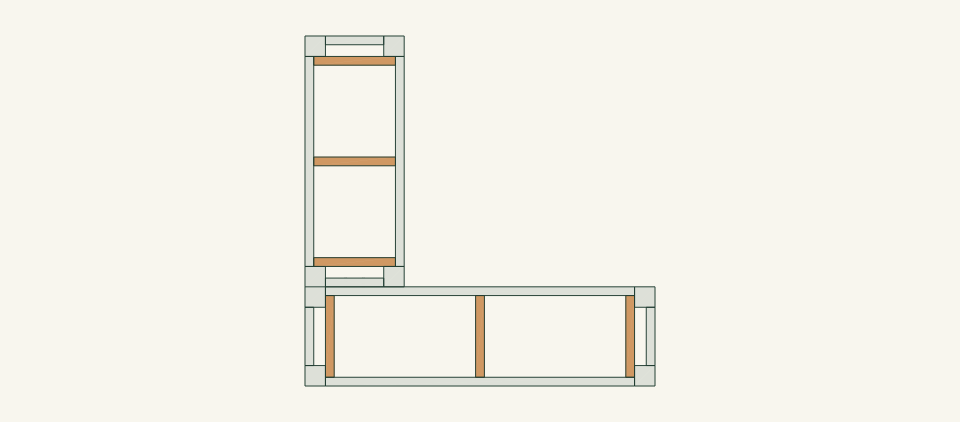
Loading the 3D view…
Drag to turn. Pinch or use + / − to zoom. The written step covers workholding and tool use.
Scroll or swipe the enlarged drawing to read its dimensions. Choose Fit to see the whole drawing again.
End cleats sit tight to the legs and the middle cleat sits at mid-length in each run.
Check: All six cleats are flush with the apron tops, and no screw tip shows on an outer apron face.
- 11
Sand and finish all parts
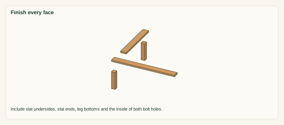
Sand the exposed faces of both frames and all six slats to 120 grit and remove the dust. If you use an exterior finish, coat every face, including slat undersides, slat ends, leg bottoms and the inside of the two bolt holes. Let it dry for the full time on the label.
Close-up · Whole model shows the complete part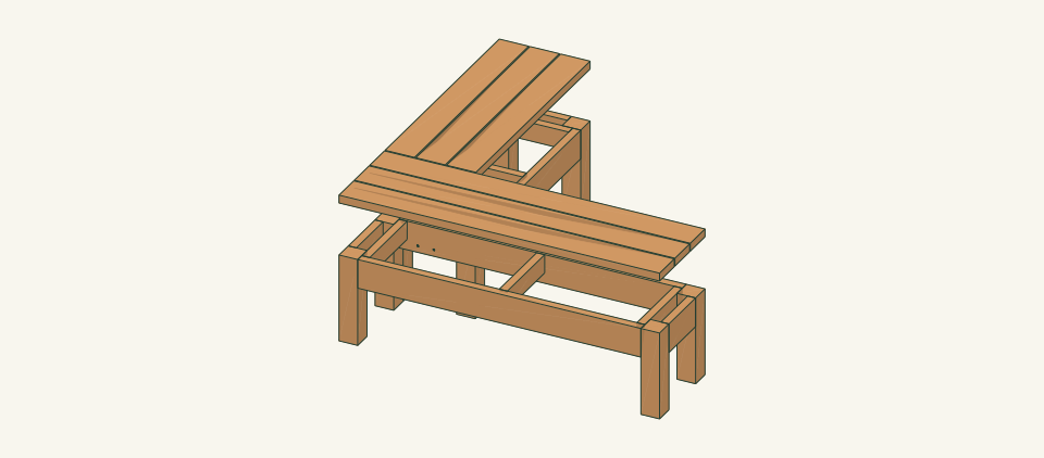
Loading the 3D view…
Drag to turn. Pinch or use + / − to zoom. The written step covers workholding and tool use.
Scroll or swipe the enlarged drawing to read its dimensions. Choose Fit to see the whole drawing again.
The slats are shown lifted 10 in only so that their undersides and ends read as finished before fastening.
Check: The finish meets the label dry standard, and no raw end grain remains on the leg bottoms or slat ends.
- 12
Fasten the seat slats
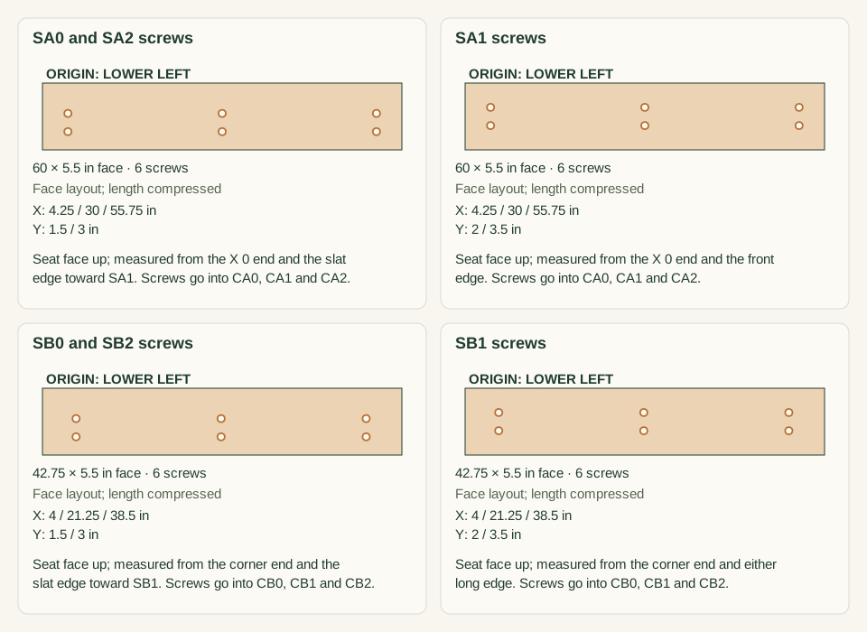
Run A: lay SA0, SA1 and SA2 with 0.25 in spacers, ends flush at X 0 and 60 and outer edges flush with the RA0 and RA1 faces. Run B: lay SB0, SB1 and SB2 with outer edges flush at X 0 and 17, back ends flush at Y 60 and front ends 0.25 in behind the EB0 outer face. Drive 2 screws per slat over each cleat centerline at the measured points, 36 in total.
Close-up · Whole model shows the complete part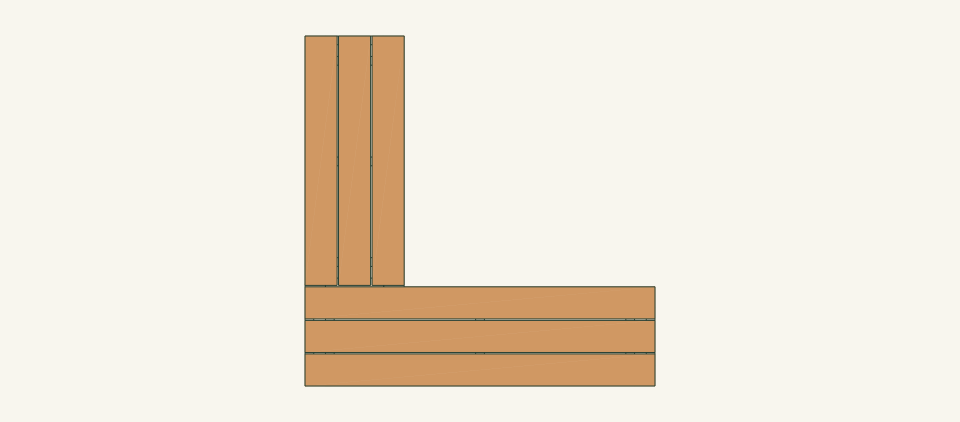
Loading the 3D view…
Drag to turn. Pinch or use + / − to zoom. The written step covers workholding and tool use.
Scroll or swipe the enlarged drawing to read its dimensions. Choose Fit to see the whole drawing again.
Outer slats are measured from their inner edge so every screw lands on a cleat, away from its end grain.
Check: Run A seat is 60 × 17 in, run B seat is 42.75 × 17 in, gaps are 0.25 in and every head is just below the seat face.
- 13
Place both runs and bolt the corner
With two people, lift run A by its aprons and set it on the checked site. Press each corner. Set run B behind it with EB0 against RA1, the outer faces flush at X 0 and all eight legs bearing. Insert both 5/16 × 4 in bolts from the RA1 side with a washer under each head. Fit a washer and lock nut on the EB0 side and tighten with a socket below cleat CB0.
Close-up · Whole model shows the complete part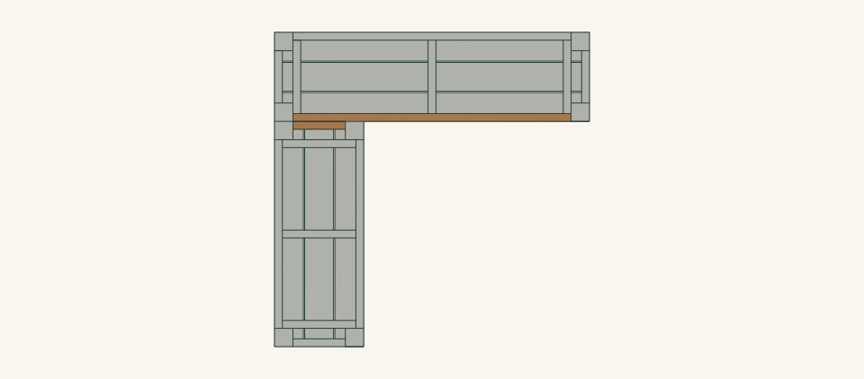
Loading the 3D view…
Drag to turn. Pinch or use + / − to zoom. The written step covers workholding and tool use.
Scroll or swipe the enlarged drawing to read its dimensions. Choose Fit to see the whole drawing again.
Bolts enter from the run A side, and the nuts sit below cleat CB0 where a socket can reach them.
Check: Each run stood without rocking before bolting. The seats are flush within 0.125 in, and both washers sit firm.
- 14
Inspect before first use
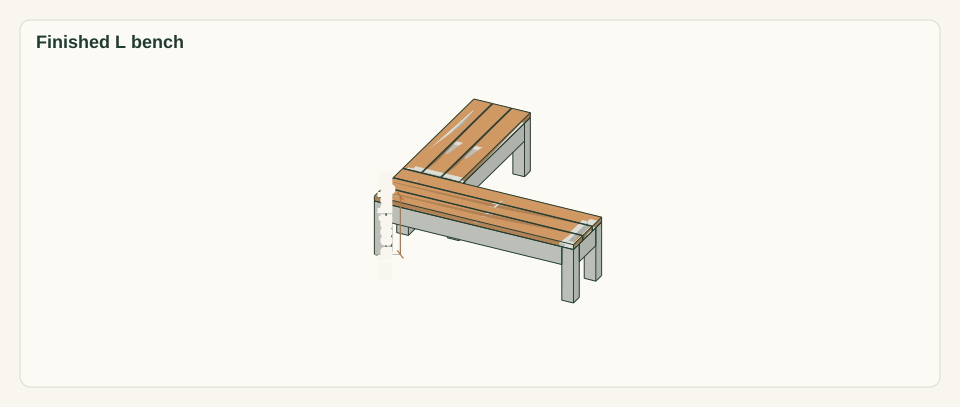
Count 56 pocket screws, 36 slat screws, 2 bolts, 4 washers and 2 nuts. Check every joint for gaps, every slat and cleat for splits, and every edge for splinters. Press down on each of the five seat corners in turn. Hold seating use until the open review in limits is recorded.
Close-up · Whole model shows the complete partLoading the 3D view…
Drag to turn. Pinch or use + / − to zoom. The written step covers workholding and tool use.
Scroll or swipe the enlarged drawing to read its dimensions. Choose Fit to see the whole drawing again.
Press the five outer seat corners and the corner joint in turn.
Check: No gap, split, protruding point or rocking is found, and the review status is recorded.


05 / Keep it sound
Care
After the build
- Set run A first and confirm that all four legs bear. Set run B and confirm the same before inserting the bolts. Never use the bolts to pull a rocking run into line.
- Do not use loose wedges under a leg. Regrade the base or move the bench if a run rocks.
Check it each season
- Check both corner nuts and every slat screw head each season and after any shift of the bench. Unload the bench before tightening a joint. Replace a cracked part rather than adding a screw beside the crack.
- Brush debris from the 0.25 in slat gaps and the corner gap so water drains. Refresh the finish as its label directs, including slat ends and leg bottoms.
If something looks wrong
- A run rocks on one leg
- Remove the corner bolts, check that run on its own, and regrade the base or move it. Check that the leg has not loosened from its aprons.
- A frame racks or an apron joint opens
- Stop using the bench. Unload and unbolt it, reclamp the joint flush and square, and replace any stripped pocket screw or damaged part.
- Corner bolt holes do not line up on site
- Check that both runs bear and that the outer faces are flush at X 0. Do not enlarge the holes or force the bolt; regrade the base until they align.
- A slat or cleat splits at a screw
- Remove the slat. Replace the split part at its listed length, then pilot and countersink before driving the screws.
- Seat tops step at the corner
- Check the base under both runs. Regrade rather than shimming, then recheck that the step is within 0.125 in.
Keep exploring