Garden benches · Guide 42
Build a Backed Garden Bench With Arms
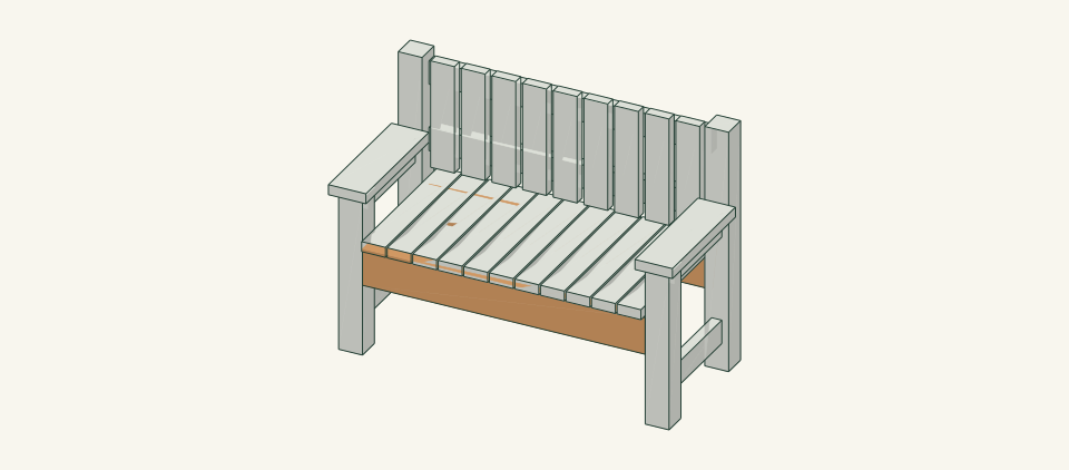
Build a 50.5-inch cedar garden bench for two, with arms at 25 inches and an upright slatted back carried on continuous 4 × 4 rear posts.
01 / See the shape
View the project
Loading the 3D view…
Drag to turn. Pinch or use + / − to zoom. The written step covers workholding and tool use.

Scroll or swipe the enlarged drawing to read its dimensions. Choose Fit to see the whole drawing again.
Lift by the aprons only, and seat all four posts on the level surface.
02 / Plan your build
Before you start
The back and arms are built into the frame. The two rear 4 × 4 posts R run from the ground to the top of the back. Both back rails K are pocket-screwed between these posts, so a push on the back goes into continuous posts rather than into a hinge joint at seat level. The front posts F rise to arm height. A 2 × 4 arm rail U ties each front post to its rear post just under the arm. Each arm A is screwed down into the long grain of U along its length, not only into the end grain of the post top. A low side rail S ties each end frame near the ground, and 2 × 6 aprons P tie the two ends at the seat. The bench fails in four main ways. Pocket joints can be driven out of square or loosen, letting the legs rack. Arm screws can miss U and hold only in end grain. Slat screws can split the slat ends. Someone can lean hard on the back or sit on an arm. Tipping and the strength of the arm and back connections have not been reviewed, so the bench is held from seating use until that review is done.
Where it goes
Firm, level paving or compacted ground with at least 30 in clear in front of the seat and no step, drop or slope within reach. Do not place it on soft soil, a raised deck edge or a slope.
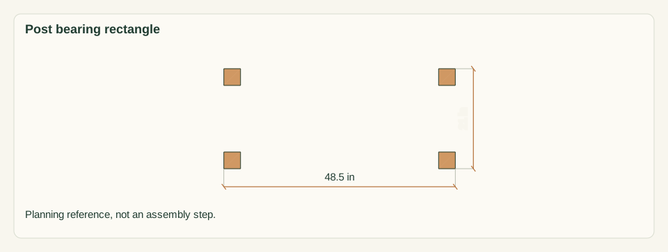
Footprint: The posts stand on a 48.5 × 21 in rectangle inside a 50.5 × 22.75 in overall outline. Allow 30 in clear in front for sitting and standing, and 24 in at each end and behind for building and cleaning
What to expect
Accurate square crosscuts, pocket-hole joinery and clamped, squared assembly. Plan 9–11 hours for one builder, with a helper for lifting and squaring, plus the finish drying time on the product label.
A planning estimate for the hands-on work, once the materials are bought and the tools are set up. It has not been timed on a finished build.
Check the spot
- Firm, level paving or compacted ground for a 48.5 × 21 in post rectangle, with 30 in clear in front and no step, drop or slope within reach.
- A flat work surface large enough to clamp a 41.5 in rail, and a helper available for steps 9 and 13.
Stop and check first if…
- Stop if a post or rail splits, a pocket screw strips, a joint opens, or the frame rocks. Unload it before opening a joint.
- Stop if an arm screw misses U or the F top, or a screw tip breaks through a face.
- Do not lengthen the bench, raise the back, add a recline or change species or section without reworking the parts, the connections and the review.
- Do not sit on the bench until the arm, back, racking and tipping review named under limits is recorded.
Work safely
- Support every 4 × 4 on both sides of the cut and clamp it. Never hold a short post offcut by hand beside the blade.
- Clamp each rail in the pocket-hole jig before drilling, and keep fingers clear of the stepped bit.
- Follow the saw, drill and finish manufacturer instructions. Keep guards in place and disconnect power before changing a bit or blade.
- Lift the assembled bench with two people by the aprons P, never by the arms or the back.
Budget
We have not put a price on this one yet. Lumber and hardware prices change by store and season, so price the list under What you need at your local supplier before you buy.
03 / Gather and cut
What you need
F — Front post
2 pieces
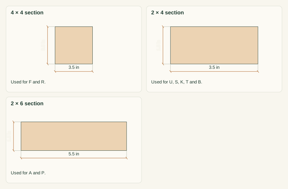
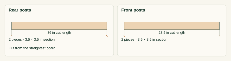
Western red cedar or redwood 4 × 4; actual 3.5 × 3.5 in. One 4 × 4 × 8-ft board: 0.5 trim + 23.5 + 0.125 kerf + 23.5 + 0.125 kerf = 47.75 in used, 48.25 in offcut.
Measure the actual section first. Mark the top end. The top end carries the arm, so reject any end with checks or splits.
R — Rear post
2 pieces
Western red cedar or redwood 4 × 4; actual 3.5 × 3.5 in. One 4 × 4 × 8-ft board: 0.5 trim + 36 + 0.125 + 36 + 0.125 = 72.75 in used. The 23.25 in offcut is too short for F.
Choose the straightest 4 × 4 for R. Bow over 0.125 in throws the back out of plane.
U — Arm rail (left and right)
2 pieces
Western red cedar or redwood 2 × 4; actual 1.5 × 3.5 in. Cut one from 2 × 4 board 4 and one from 2 × 4 board 5 (see the 2 × 4 layout calculation).
Mark the parts L and R. Pocket holes go on the face toward the seat, so the pair is mirrored.
S — Low side rail (left and right)
2 pieces
Western red cedar or redwood 2 × 4; actual 1.5 × 3.5 in. Cut both from 2 × 4 board 6.
Mark the parts L and R. Pocket holes go on the face toward the seat.
A — Arm
2 pieces
Western red cedar or redwood 2 × 6; actual 1.5 × 5.5 in. Second 2 × 6 board (any length of 4 ft or more): 0.5 + 18.5 + 0.125 + 18.5 + 0.125 = 37.75 in used.
Choose clear, splinter-free stock. Arms are hand-contact surfaces. Round the top edges and front corners after cutting.
P — Seat apron (front and rear)
2 pieces
Western red cedar or redwood 2 × 6; actual 1.5 × 5.5 in, set on edge. One 2 × 6 × 8-ft board: 0.5 + 41.5 + 0.125 + 41.5 + 0.125 = 83.75 in used.
Set the crown, if any, upward. Reject a board with a knot in the lower third near mid-length.
K — Back rail (lower and upper)
2 pieces
Western red cedar or redwood 2 × 4; actual 1.5 × 3.5 in. 2 × 4 board 1: 0.5 + 41.5 + 0.125 + 41.5 + 0.125 = 83.75 in used.
Both rails must be straight within 0.125 in so that the back slats sit flat.
T — Seat slat
11 pieces
Western red cedar or redwood 2 × 4; actual 1.5 × 3.5 in, laid flat, running front to back. Four each from 2 × 4 boards 2 and 3, and three from board 4: 4 + 4 + 3 = 11.
Reject ends with splits within 2 in. Screws sit 0.75 in from the slat ends over the aprons. Mark the show face.
B — Back slat
9 pieces
Western red cedar or redwood 2 × 4; actual 1.5 × 3.5 in, standing vertical. Five from 2 × 4 board 5 and four from board 6: 5 + 4 = 9.
Mark the show face and the bottom end. Ease all front edges.
Pocket screws
32 items
2.5 in coarse-thread pocket screws, stainless steel, rated for exterior use Buy at least 32 and keep spares separate.
U and S to F and R: 16. P to the posts: 8. K to R: 8. Follow the jig and screw instructions. No joint capacity is inferred.
Arm screws
10 items
#10 × 3.5 in wood screws, stainless steel, exterior Buy at least 10.
Five per arm A: two into the F top and three into U. Clearance hole through A, pilot into the receiving part.
Slat screws
80 items
#10 × 2.5 in deck screws, stainless steel, exterior Buy at least 80.
Seat: 11 T × 4 = 44. Back: 9 B × 4 = 36. Pilot and countersink every hole.
Cut list
| Piece | How many | Cut length | Note |
|---|---|---|---|
| F — Front post | 2 | 23.5 × 3.5 × 3.5 in | Finished length × width × thickness; square ends unless the detail says otherwise. |
| R — Rear post | 2 | 36 × 3.5 × 3.5 in | Finished length × width × thickness; square ends unless the detail says otherwise. |
| U — Arm rail (left and right) | 2 | 14 × 3.5 × 1.5 in | Finished length × width × thickness; square ends unless the detail says otherwise. |
| S — Low side rail (left and right) | 2 | 14 × 3.5 × 1.5 in | Finished length × width × thickness; square ends unless the detail says otherwise. |
| A — Arm | 2 | 18.5 × 5.5 × 1.5 in | Finished length × width × thickness; square ends unless the detail says otherwise. |
| P — Seat apron (front and rear) | 2 | 41.5 × 5.5 × 1.5 in | Finished length × width × thickness; square ends unless the detail says otherwise. |
| K — Back rail (lower and upper) | 2 | 41.5 × 3.5 × 1.5 in | Finished length × width × thickness; square ends unless the detail says otherwise. |
| T — Seat slat | 11 | 22.5 × 3.5 × 1.5 in | Finished length × width × thickness; square ends unless the detail says otherwise. |
| B — Back slat | 9 | 16 × 3.5 × 1.5 in | Finished length × width × thickness; square ends unless the detail says otherwise. |
Tools
- Tape measure, combination square, framing square and pencil
- 4-ft level and a straightedge
- Guarded circular saw or miter saw with capacity for 3.5 in stock
- Pocket-hole jig with stepped bit and depth collar
- Drill/driver, countersink pilot bits matched to the #10 screws and a clearance bit
- At least four bar clamps of 24 in or longer, plus two of 48 in or longer
- Sander or sanding block with 120-grit abrasive, and a router or rasp for edge rounding
- Spacers: 0.25 in, 1.0 in and two 2 in blocks
Protective gear
- Eye protection during all cutting, drilling and driving
- Hearing protection when using the saw
- Dust mask when sanding cedar or redwood; the dust can irritate airways
- Closed footwear. Keep loose sleeves and gloves away from rotating bits and blades.
04 / Put it together
Build steps
- 01
Confirm the site and use
Choose firm, level paving or compacted ground at least 50.5 × 22.75 in, with 30 in clear in front. Lay a straightedge and level across the 48.5 × 21 in rectangle where posts F and R will stand. Check both directions and both diagonals. Plan the bench for seated use by people who can sit and stand unaided.
Close-up · Whole model shows the complete part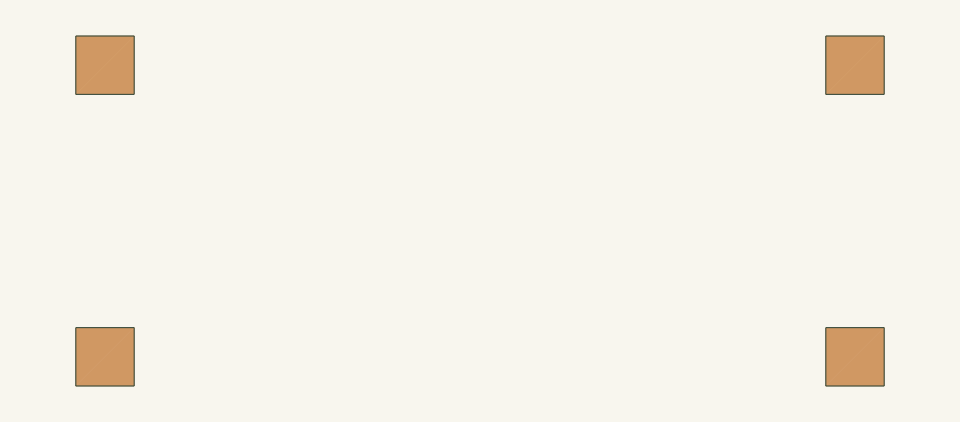
Loading the 3D view…
Drag to turn. Pinch or use + / − to zoom. The written step covers workholding and tool use.
Scroll or swipe the enlarged drawing to read its dimensions. Choose Fit to see the whole drawing again.
Planning reference only: the four post positions show the ground rectangle to level.
Check: The surface is level within the bubble both ways, firm underfoot and clear of steps, drops and slopes.
- 02
Inspect and measure the stock
Measure every board at both ends and the middle. The 4 × 4 must be 3.5 × 3.5 in, the 2 × 4 1.5 × 3.5 in and the 2 × 6 1.5 × 5.5 in. Reject boards with splits within 6 in of an end, loose knots, twist, or bow over 0.125 in. Number the six 2 × 4 boards 1 to 6 for the cut layout.
Close-up · Whole model shows the complete part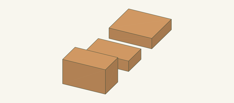
Loading the 3D view…
Drag to turn. Pinch or use + / − to zoom. The written step covers workholding and tool use.
Scroll or swipe the enlarged drawing to read its dimensions. Choose Fit to see the whole drawing again.
Compare each actual section with the three sizes used in this bench.
Check: Every section matches the parts table, or work stops until the lengths are reworked for the stock on hand.
- 03
Cut the four posts
Square one end of each 4 × 4 first. Support the board on both sides of the cut and clamp it. From the straightest board, cut two rear posts R at 36 in. From the second board, cut two front posts F at 23.5 in. Ease the bottom edges of all four posts 0.25 in. Label each post and mark its top end.
Close-up · Whole model shows the complete part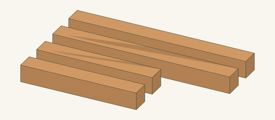
Loading the 3D view…
Drag to turn. Pinch or use + / − to zoom. The written step covers workholding and tool use.
Scroll or swipe the enlarged drawing to read its dimensions. Choose Fit to see the whole drawing again.
Four posts from two 4 × 4 boards, top ends marked.
Check: Paired posts match within 0.0625 in, and each end is square to two adjacent faces.
- 04
Cut the rails, aprons and arms
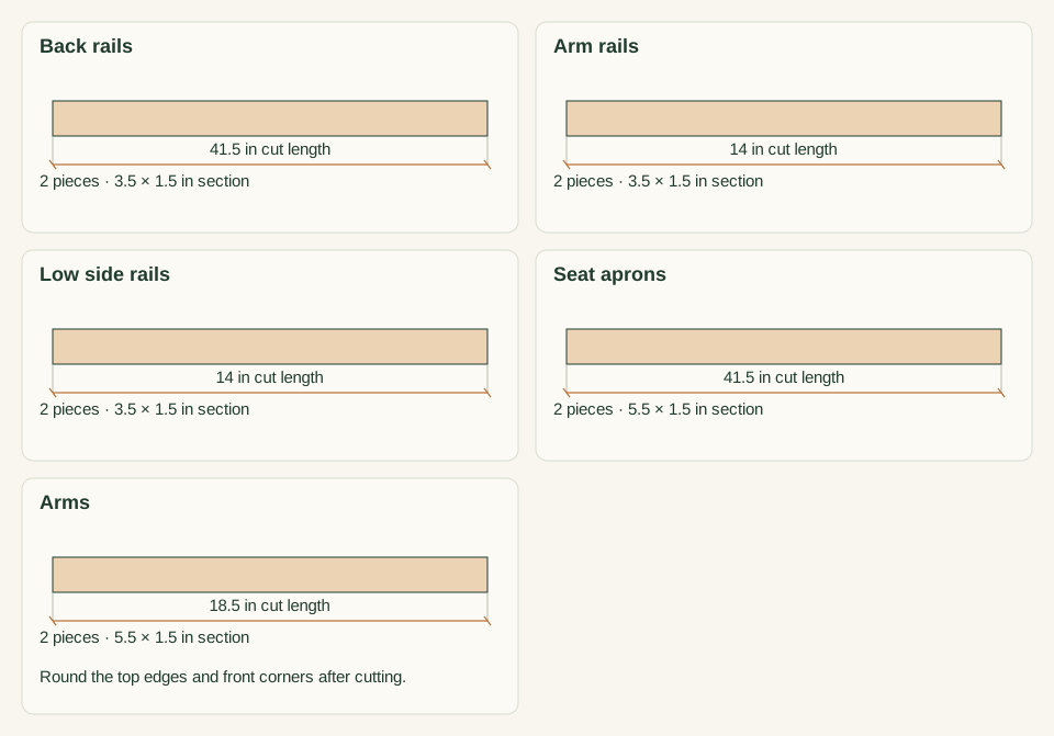
From 2 × 4 board 1, cut two back rails K at 41.5 in. Cut one arm rail U at 14 in from board 4 and one from board 5. Cut two low side rails S at 14 in from board 6. From the 8-ft 2 × 6, cut two aprons P at 41.5 in. From the second 2 × 6, cut two arms A at 18.5 in. Round the A top edges and front corners. Label U, S and A as left and right.
Close-up · Whole model shows the complete part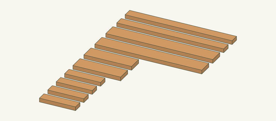
Loading the 3D view…
Drag to turn. Pinch or use + / − to zoom. The written step covers workholding and tool use.
Scroll or swipe the enlarged drawing to read its dimensions. Choose Fit to see the whole drawing again.
Frame rails, aprons and arms, labeled left and right where mirrored.
Check: K and P pairs match within 0.0625 in, U and S all read 14 in, and both A read 18.5 in.
- 05
Cut the seat and back slats
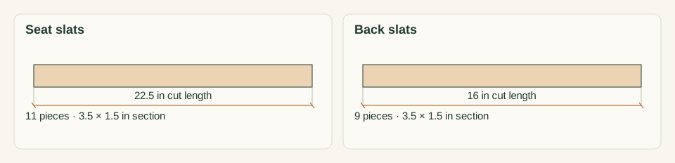
Cut four seat slats T at 22.5 in from each of 2 × 4 boards 2 and 3, and three from the rest of board 4, for 11. Cut five back slats B at 16 in from the rest of board 5 and four from the rest of board 6, for 9. Mark each show face. Ease the edges and ends 0.125 in.
Close-up · Whole model shows the complete part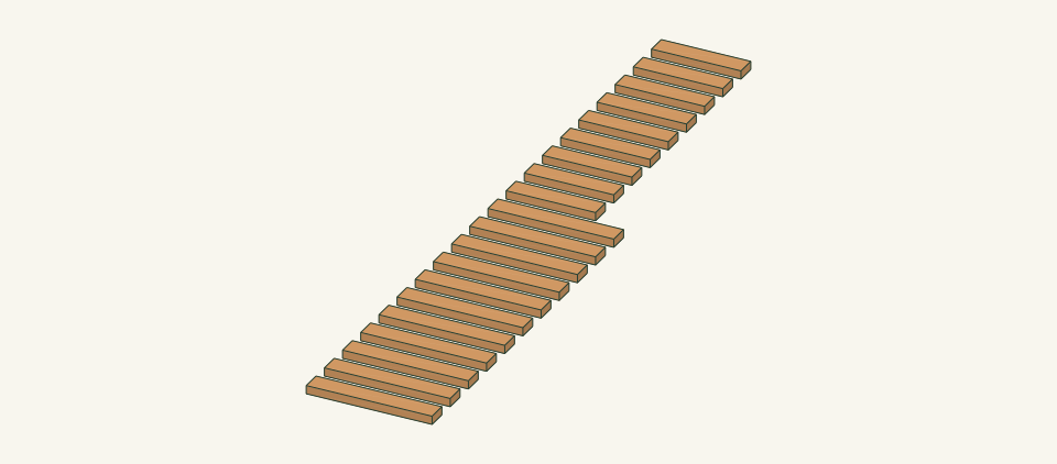
Loading the 3D view…
Drag to turn. Pinch or use + / − to zoom. The written step covers workholding and tool use.
Scroll or swipe the enlarged drawing to read its dimensions. Choose Fit to see the whole drawing again.
Seat and back slats, show faces marked.
Check: Eleven T and nine B lie flat, with lengths within 0.0625 in and no end splits.
- 06
Drill the pocket holes
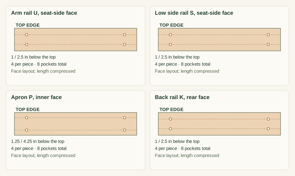
Set the jig and drill collar for 1.5 in stock per the jig instructions. On U and S, drill two holes at each end on the seat-side face, 1.0 and 2.5 in below the top edge. On P, drill two at each end on the inner face, 1.25 and 4.25 in below the top edge. On K, drill two at each end on the rear face, 1.0 and 2.5 in below the top edge.
Close-up · Whole model shows the complete part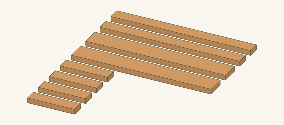
Loading the 3D view…
Drag to turn. Pinch or use + / − to zoom. The written step covers workholding and tool use.
Scroll or swipe the enlarged drawing to read its dimensions. Choose Fit to see the whole drawing again.
Pocket-hole rows on each rail, on the face that stays hidden.
Check: Count 32 holes, all on the marked faces, with left and right U and S mirrored and no breakout.
- 07
Sand and finish the parts
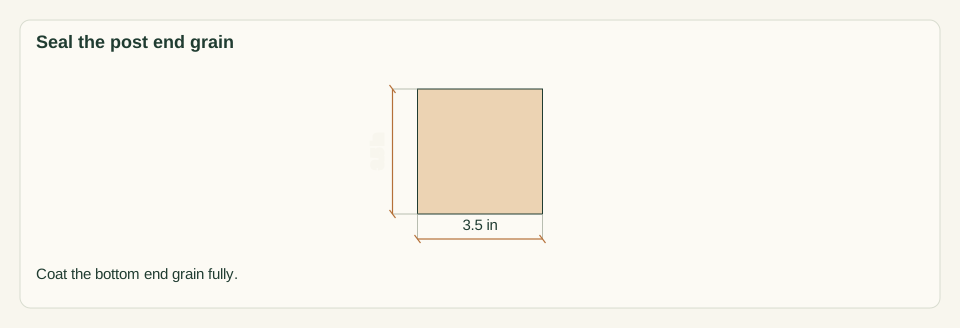
Sand all faces of F, R, U, S, A, P, K, T and B to 120 grit and remove the dust. If using an exterior finish, coat every face, edge and end, including the post bottoms and the end grain of every slat, before assembly. Let it dry for the full time on the product label.
Close-up · Whole model shows the complete part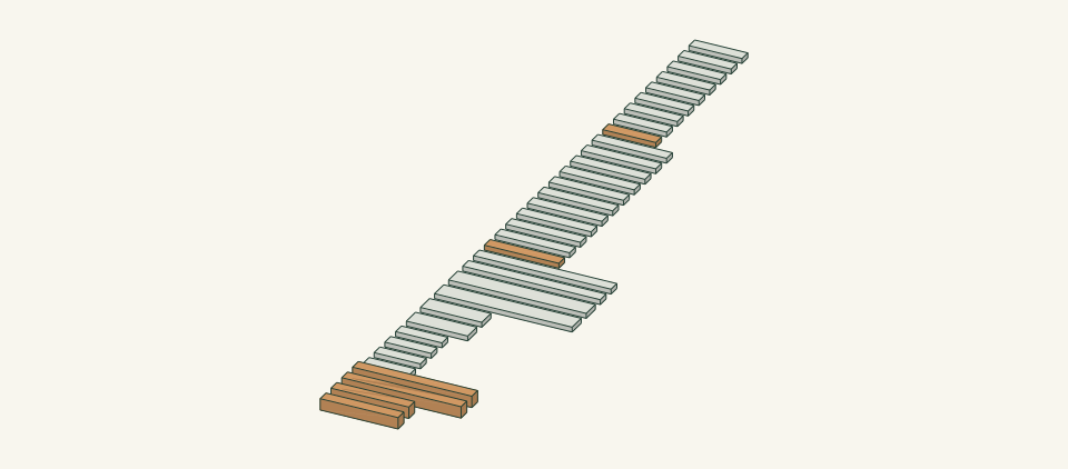
Loading the 3D view…
Drag to turn. Pinch or use + / − to zoom. The written step covers workholding and tool use.
Scroll or swipe the enlarged drawing to read its dimensions. Choose Fit to see the whole drawing again.
Coat every face and end before assembly, including the post bottoms.
Check: The finish is dry to the label standard and no raw end grain remains on the post bottoms.
- 08
Assemble the two end frames
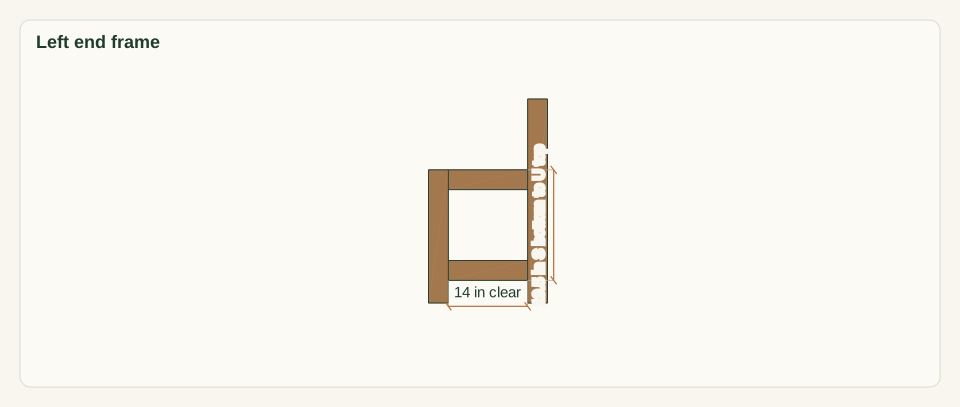
Lay the left F and R on a flat bench, seat-side faces up, 14 in apart between faces, bottoms aligned. Clamp S between them with its bottom edge 4 in above the post bottoms. Clamp U with its top flush with the F top, from 20 to 23.5 in. Center both rails 1.0 in from each post face. Drive two pocket screws per rail end, 8 per frame. Repeat mirrored for the right end.
Close-up · Whole model shows the complete part
Loading the 3D view…
Drag to turn. Pinch or use + / − to zoom. The written step covers workholding and tool use.
Scroll or swipe the enlarged drawing to read its dimensions. Choose Fit to see the whole drawing again.
S low and U high, centered on the posts with pocket holes inside.
Check: The opening diagonals from the S bottom to the U top read 24.0 in and match within 0.0625 in.
- 09
Join the ends with aprons and back rails
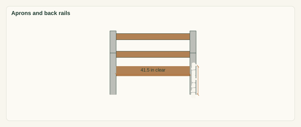
With a helper, stand both end frames 41.5 in apart between the inner post faces. Clamp the front P flush with the F front faces, top edge 16 in above the floor. Clamp the rear P flush with the R rear faces at the same height. Clamp the lower K flush with the R rear faces at 21 to 24.5 in, and the upper K at 31 to 34.5 in. Drive 16 pocket screws.
Close-up · Whole model shows the complete part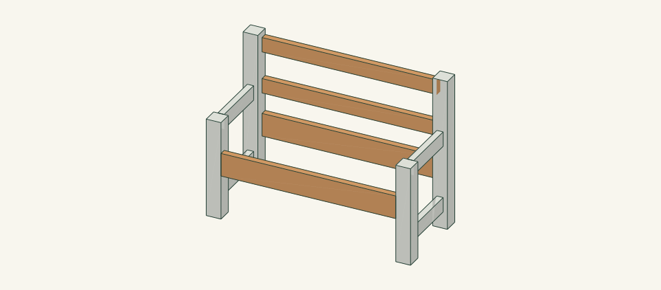
Loading the 3D view…
Drag to turn. Pinch or use + / − to zoom. The written step covers workholding and tool use.
Scroll or swipe the enlarged drawing to read its dimensions. Choose Fit to see the whole drawing again.
The aprons tie the ends at seat level, and both back rails tie the rear posts.
Check: The outside post diagonals read 52.85 in and match within 0.125 in, and all four feet touch the floor.
- 10
Fasten the arms
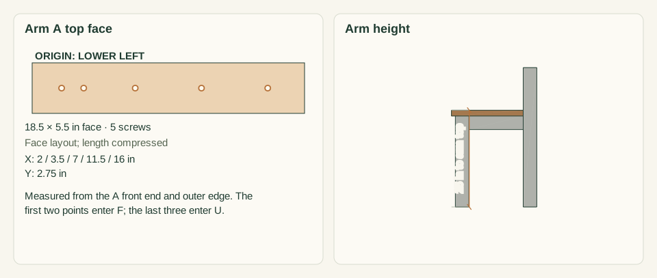
Set each A on the F top with its rear end butted to the R front face, overhanging 1 in at the front and 1 in past each F side face. Clamp A to U. Mark five points on the A centerline, 2.75 in from the edge, at 2, 3.5, 7, 11.5 and 16 in from the front end. Drill clearance holes through A and pilots into F and U. Drive five #10 × 3.5 in screws per arm.
Close-up · Whole model shows the complete part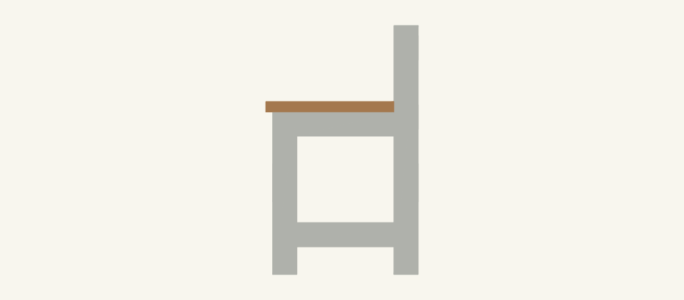
Loading the 3D view…
Drag to turn. Pinch or use + / − to zoom. The written step covers workholding and tool use.
Scroll or swipe the enlarged drawing to read its dimensions. Choose Fit to see the whole drawing again.
Each arm screws into the post top and along the arm rail.
Check: Each A sits flat with its top 25 in above the floor, and no screw tip shows on the U or F faces.
- 11
Fasten the seat slats
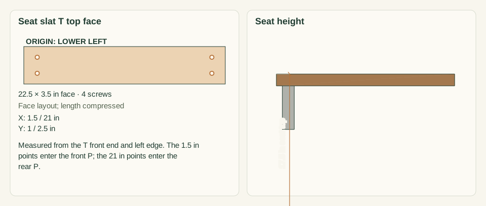
Lay the T slats across both P, show face up, with front ends 0.75 in in front of the front apron. Set the first T 0.25 in from the left post inner faces and space the rest with 0.25 in spacers. Mark four points per slat, 1.5 and 21 in from the front end and 1.0 and 2.5 in from the left edge. Pilot, countersink and drive 44 #10 × 2.5 in screws.
Close-up · Whole model shows the complete part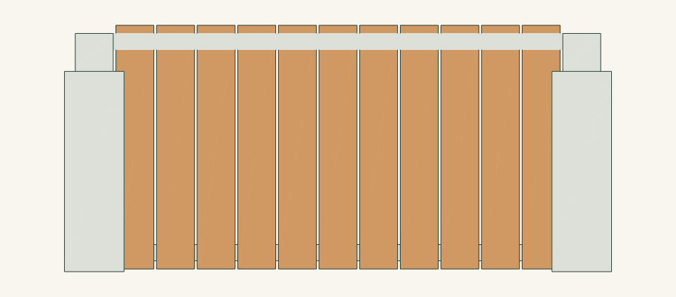
Loading the 3D view…
Drag to turn. Pinch or use + / − to zoom. The written step covers workholding and tool use.
Scroll or swipe the enlarged drawing to read its dimensions. Choose Fit to see the whole drawing again.
Seat slats run front to back over both aprons with even 0.25 in gaps.
Check: The seat top is 17.5 in, all 12 gaps are 0.25 in, and every head sits just below the surface.
- 12
Fasten the back slats
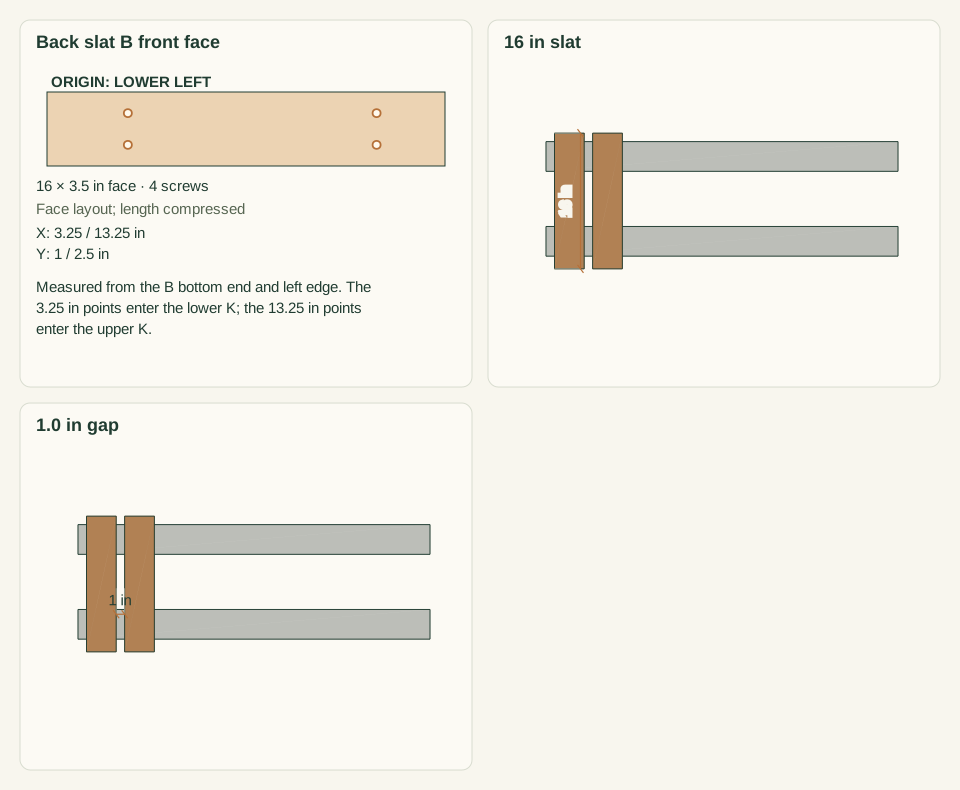
Set 2 in spacer blocks on the seat. Stand each B on them, against the front faces of both K, so that the bottom end is 19.5 in above the floor. Set the first B 1.0 in from the left post and space the rest 1.0 in apart. Mark four points per slat, 3.25 and 13.25 in from the bottom end and 1.0 and 2.5 in from the left edge. Pilot, countersink and drive 36 #10 × 2.5 in screws.
Close-up · Whole model shows the complete part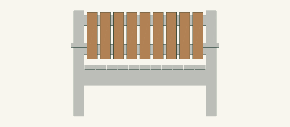
Loading the 3D view…
Drag to turn. Pinch or use + / − to zoom. The written step covers workholding and tool use.
Scroll or swipe the enlarged drawing to read its dimensions. Choose Fit to see the whole drawing again.
Back slats stand on 2 in blocks and screw to both back rails.
Check: All ten gaps are 1.0 in, the B tops are at 35.5 in, and no tip breaks through the rear face of K.
- 13
Place and level the bench
With two people, lift the bench by the aprons P, never by the arms A or the back slats B, and set it on the checked site. Press down on each seat corner in turn. Do not use loose wedges under a post. If the bench rocks, regrade the surface or move the bench.
Close-up · Whole model shows the complete partLoading the 3D view…
Drag to turn. Pinch or use + / − to zoom. The written step covers workholding and tool use.
Scroll or swipe the enlarged drawing to read its dimensions. Choose Fit to see the whole drawing again.
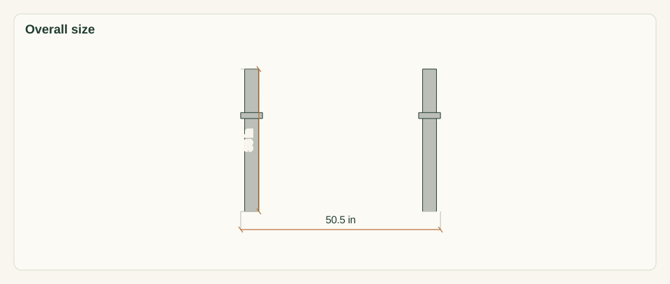
Lift by the aprons only, and seat all four posts on the level surface.
Check: All four posts bear on the surface with no rocking when each corner is pressed.
- 14
Inspect and hold for review
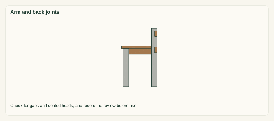
Count 32 pocket screws, 10 arm screws and 80 slat screws, all seated, with no tips breaking a surface. Check every rail joint for gaps and every slat end for splits. Run a hand over the arms, seat and back. Confirm that the arm, back, racking and tipping review named under limits is recorded before anyone sits on the bench.
Close-up · Whole model shows the complete part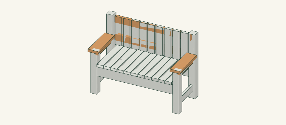
Loading the 3D view…
Drag to turn. Pinch or use + / − to zoom. The written step covers workholding and tool use.
Scroll or swipe the enlarged drawing to read its dimensions. Choose Fit to see the whole drawing again.
The arm and back joints are the connections held for review.
Check: No gap, split, protruding point or rocking is found, and the review is recorded before first use.


05 / Keep it sound
Care
After the build
- Place the bench only on the checked level surface. Re-check for rocking after any move.
- Before first use, confirm the review recorded in step 14. Sit near the middle for the first trial, then try each seat place. Do not sit on an arm or lean back hard against the top of the back.
Check it each season
- Inspect every pocket-screw joint, all 10 arm screws and the slat ends each season and after any wobble. Unload the bench before tightening. Replace a cracked part rather than adding a screw beside the crack.
- Brush debris from the seat and back gaps and from around the post bottoms. Recoat finished surfaces when water no longer beads, following the finish label.
If something looks wrong
- Bench rocks on one corner
- Move it to level ground or regrade the surface. Check that no post has loosened from its rails.
- Arm moves when pressed
- Stop using the bench. Check the five A screws and the U pocket joints, and replace any stripped screw. Do not rely on the F top screws alone.
- Back flexes or a K joint opens
- Stop using the bench. Unload it, reclamp K flush to R and replace any stripped pocket screw. Refer repeated movement for review.
- Seat slat splits at a screw
- Remove the slat and cut a replacement at 22.5 in. Pilot and countersink before driving the screws.
- Screw head rises above a surface
- Reset it just below the surface. Replace the screw if it no longer holds.
Keep exploring