Garden tools and jigs · Guide 119
Build an Adjustable Two-Row Marking Rake
Two retained blunt markers slide along measured slots to transfer a crop-selected row spacing.
01 / See the shape
View the project
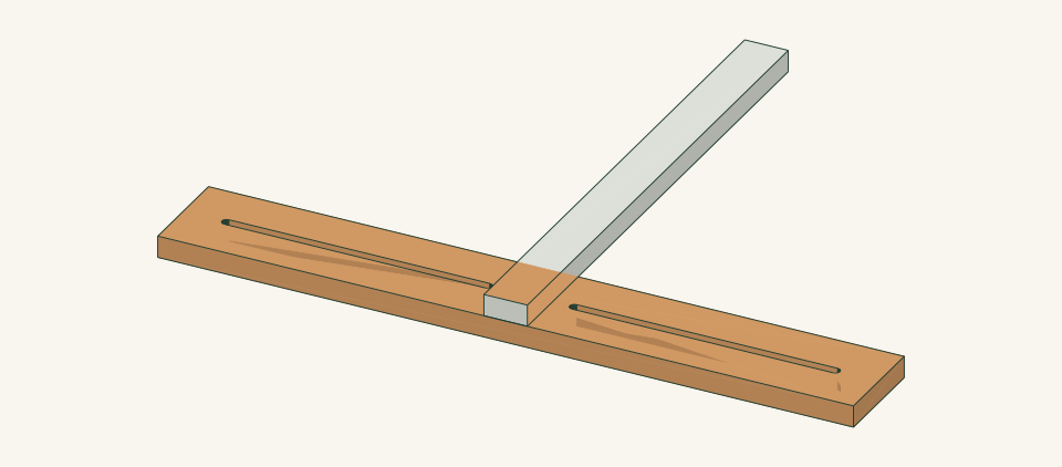
Loading the 3D view…
Drag to turn. Pinch or use + / − to zoom. The written step covers workholding and tool use.
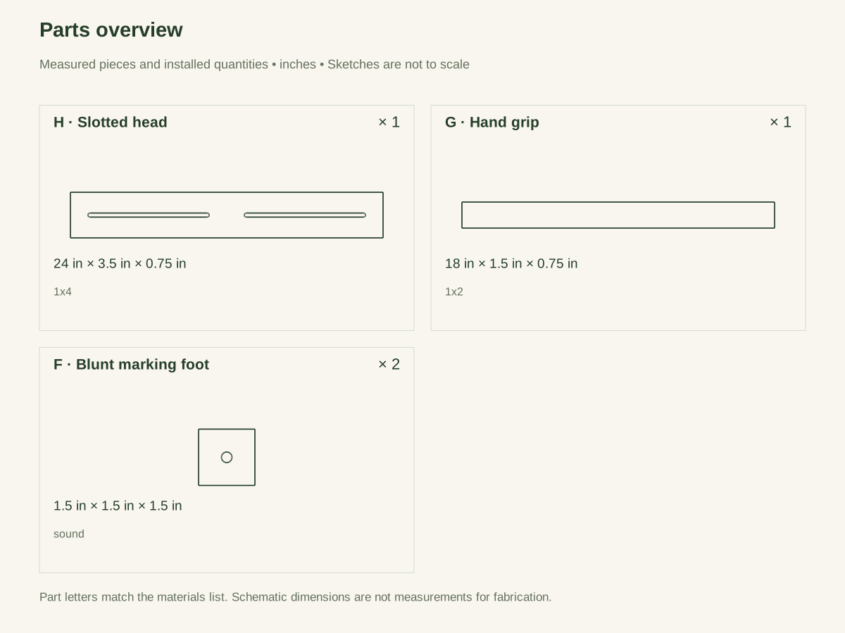
Scroll or swipe the enlarged drawing to read its dimensions. Choose Fit to see the whole drawing again.
Build an Adjustable Two-Row Marking Rake. Check the dimensions and build steps before cutting.
02 / Plan your build
Before you start
Two adjustable markers are enough to establish parallel seed rows while keeping the tool simple. Broad rounded wooden feet make shallow marks in prepared medium. Captive bolts and wing nuts hold the selected spacing; the tool does not cut furrows or probe unknown ground.
Where it goes
Prepared loose growing medium with known conditions, clear of stones, buried lines and existing seedlings; temporary marking only.
Footprint: 24 × 18 in frame size; allow room around it to work and for anything that projects.
What to expect
Measure accurately, make supported square cuts and drill clamped joints. Plan 2–3 hours for supported slot cutting and adjustment trials.
A planning estimate for the hands-on work, once the materials are bought and the tools are set up. It has not been timed on a finished build.
Check the spot
- Prepared loose growing medium with known conditions, clear of stones, buried lines and existing seedlings; temporary marking only.
- Measure the usable stock before marking. Keep the assembly area flat and large enough to clamp the work without reaching across a moving cutter.
Stop and check first if…
- Stop if a part splits, a fixing strips, or the assembled object rocks. Unload it before opening a joint.
- Do not substitute an unknown material section or make the object taller or wider without checking every affected part and joint.
Work safely
- Hold each small foot in a clamped jig; never grip it beside a turning bit. Unplug or stop the drill before clearing chips and keep the coping-saw blade supported away from hands.
- Use only shallow marks in known loose growing medium. Do not force the feet past stones or probe unknown ground. Retain nuts and washers during storage and keep small hardware away from children.
Budget
We have not put a price on this one yet. Lumber and hardware prices change by store and season, so price the list under What you need at your local supplier before you buy.
03 / Gather and cut
What you need
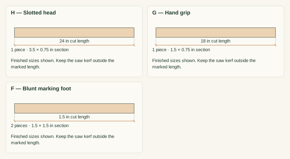
H — Slotted head
1 piece
Straight untreated 1 × 4, actual 0.75 × 3.5. Buy one nominal 1 × 4 × 4-ft board, actual 0.75 × 3.5 in, for the 24-inch head.
Measure your boards before cutting. Build to the finished sizes written here, not the nominal lumber label.
G — Hand grip
1 piece
Straight untreated 1 × 2, actual 0.75 × 1.5. Buy one nominal 1 × 2 × 4-ft board, actual 0.75 × 1.5 in, for the 18-inch grip.
Measure your boards before cutting. Build to the finished sizes written here, not the nominal lumber label.
F — Blunt marking foot
2 pieces
Sound untreated 1.5-inch-square solid wood. Use one sound 2 × 2 offcut at least 8 inches long for two 1.5-inch cubes plus kerf and safe workholding.
Round lower edges by hand; do not fit metal spikes or sharp tines.
K — Captive bolt/wingnut assembly
2 pieces
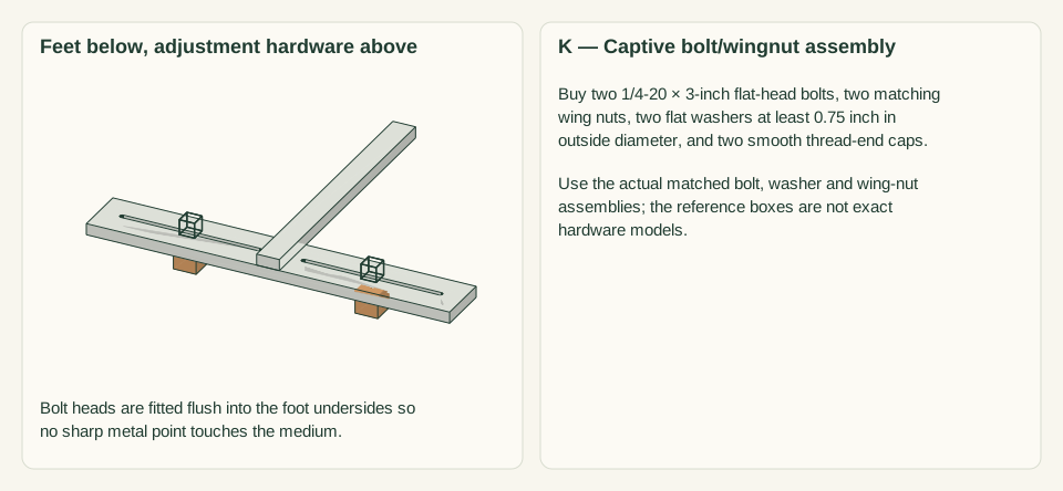
1/4-20 × 3-inch flat-head stainless bolts, flat washers and matching wing nuts; cover unused sharp thread ends if necessary. Buy two 1/4-20 × 3-inch flat-head bolts, two matching wing nuts, two flat washers at least 0.75 inch in outside diameter, and two smooth thread-end caps.
Choose the countersink angle to match the actual bolt heads. Washers must span the slots; caps cover unused sharp thread without preventing wing-nut adjustment.
Grip screws
4 items
#6 × 1.25-in wood screws Purchase at least 4; keep spare hardware separate from the installed count.
Use one consistent product and follow its pilot and driving instructions.
Spacing labels
1 item
Fine durable marker for slot centers and selected row settings Buy one fine waterproof marker suitable for dry wood.
Write the measured center marks and selected settings; do not assume an old setting is still correct.
Cut list
| Piece | How many | Cut length | Note |
|---|---|---|---|
| H — Slotted head | 1 | 24 × 3.5 × 0.75 in | Finished length × width × thickness; square ends unless the detail says otherwise. |
| G — Hand grip | 1 | 18 × 1.5 × 0.75 in | Finished length × width × thickness; square ends unless the detail says otherwise. |
| F — Blunt marking foot | 2 | 1.5 × 1.5 × 1.5 in | Finished length × width × thickness; square ends unless the detail says otherwise. |
Tools
- Tape or rule, square and sharp pencil
- Clamps, a flat bench and sacrificial backing
- Suitable guarded saw for the specified stock
- Drill/driver, depth stop and bits matched to the chosen screws
- Fine abrasive and a dust brush
- Coping saw with a blade narrow enough for a 5/16-inch hole; narrow flat file;5/16-inch and 9/32-inch drill bits; matching bolt-head countersink; clamped cube-holding jig
Protective gear
- Eye protection during cutting and drilling
- Hearing protection and dust collection appropriate to the actual tools
- Closed footwear; keep loose clothing and gloves away from rotating cutters
04 / Put it together
Build steps
- 01
Choose and record row spacing
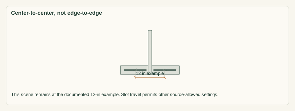
Read the actual crop guidance and choose the row-center distance. The drawing’s 12-inch spacing is only a mechanical example. Check that the chosen distance fits the two separate slot ranges without crowding the grip.
Close-up · Whole model shows the complete part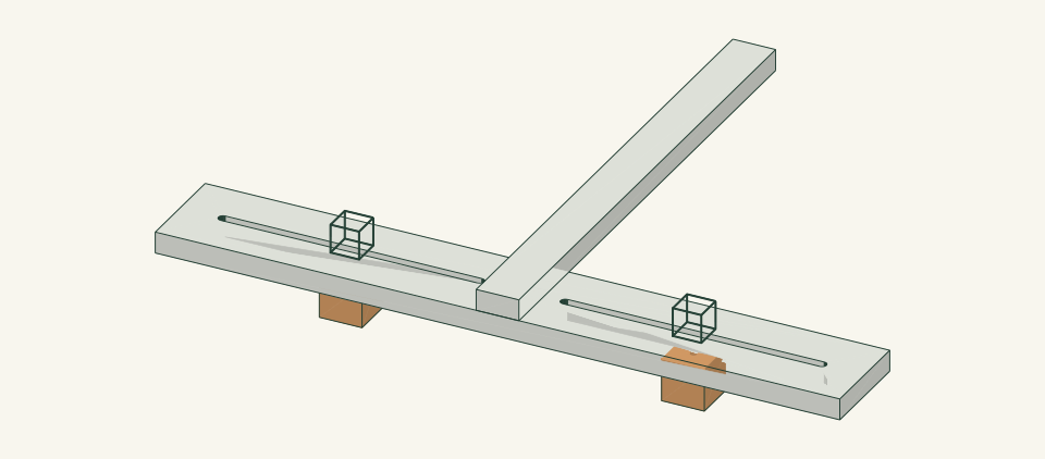
Loading the 3D view…
Drag to turn. Pinch or use + / − to zoom. The written step covers workholding and tool use.
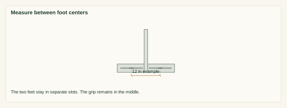
Scroll or swipe the enlarged drawing to read its dimensions. Choose Fit to see the whole drawing again.
Choose row spacing from the crop instructions. The 12-in setting in this model is a mechanical example, not a planting recommendation.
Check: The spacing comes from crop instructions and can be set within the slot travel.
- 02
Cut the head, grip and blunt feet
Cut a 24-inch head, 18-inch grip and two 1.5-inch cubes from the stated actual sections. Mark the head’s left/front starting edge. Round the feet’s lower edges gently without changing the bolt centerline.
Close-up · Whole model shows the complete part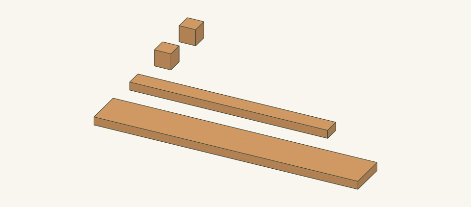
Loading the 3D view…
Drag to turn. Pinch or use + / − to zoom. The written step covers workholding and tool use.
Scroll or swipe the enlarged drawing to read its dimensions. Choose Fit to see the whole drawing again.
Cut the head, grip and two wooden feet as separate blanks. No slots or bores are present before their own operations.
Check: All pieces are sound and the two feet are blunt rather than pointed.
- 03
Mark both slots from one starting edge
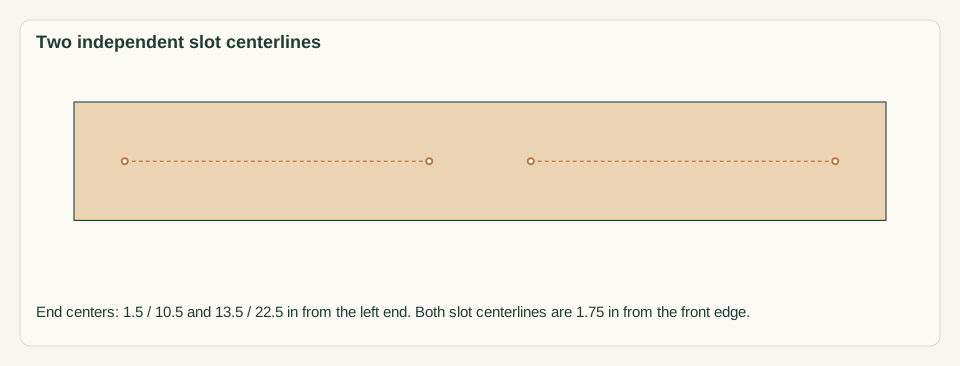
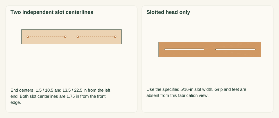
Draw the slot centerline 1.75 inches from the head front. Mark left-slot endpoints 1.5 and 10.5 inches and right endpoints 13.5 and 22.5. Mark the grip screw rectangle separately so no hole intersects a slot.
Close-up · Whole model shows the complete part
Loading the 3D view…
Drag to turn. Pinch or use + / − to zoom. The written step covers workholding and tool use.
Scroll or swipe the enlarged drawing to read its dimensions. Choose Fit to see the whole drawing again.
Mark the slot endpoints on the uncut head before passing the coping-saw blade through a drilled end hole.
Check: Both slots are parallel and remain clear of the center fastening area.
- 04
Cut slots with a coping saw
Clamp the head flat over sacrificial backing. Drill the four 5/16-inch end holes at the marked centers. Release one end of a narrow coping-saw blade, pass it through an end hole and refit it in its frame. Saw just inside the two connecting slot lines with the wood fully supported. File to the lines, keeping width 5/16 inch; leave the drilled rounded ends intact.
Close-up · Whole model shows the complete part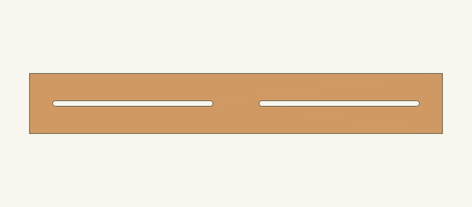
Loading the 3D view…
Drag to turn. Pinch or use + / − to zoom. The written step covers workholding and tool use.
Scroll or swipe the enlarged drawing to read its dimensions. Choose Fit to see the whole drawing again.
Drill the four end holes and connect each pair with the supported coping-saw cuts. The head now shows two real rounded slots.
Check: Both 1/4-inch bolts slide in their own slots without forcing, and no slot end is split.
- 05
Drill and recess both wooden feet
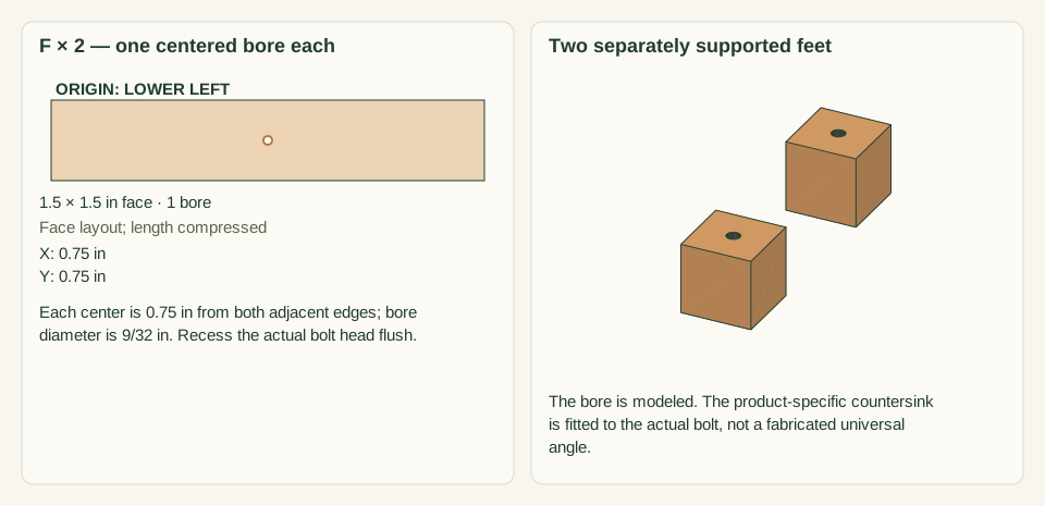
Clamp each cube in a holding jig over backing. Mark its center 0.75 inch from both adjacent edges and drill a 9/32-inch through-hole. Use a countersink bit matching the chosen flat bolt head angle, cutting only until the head is flush with the underside. Check the actual bolt before repeating.
Close-up · Whole model shows the complete part
Loading the 3D view…
Drag to turn. Pinch or use + / − to zoom. The written step covers workholding and tool use.
Scroll or swipe the enlarged drawing to read its dimensions. Choose Fit to see the whole drawing again.
Drill the centered foot bores while each small block is clamped, then fit the countersink to the actual bolt head.
Check: Bolt heads sit flush, sound wood surrounds both holes and no sharp metal touches the soil.
- 06
Mark and fasten the central grip
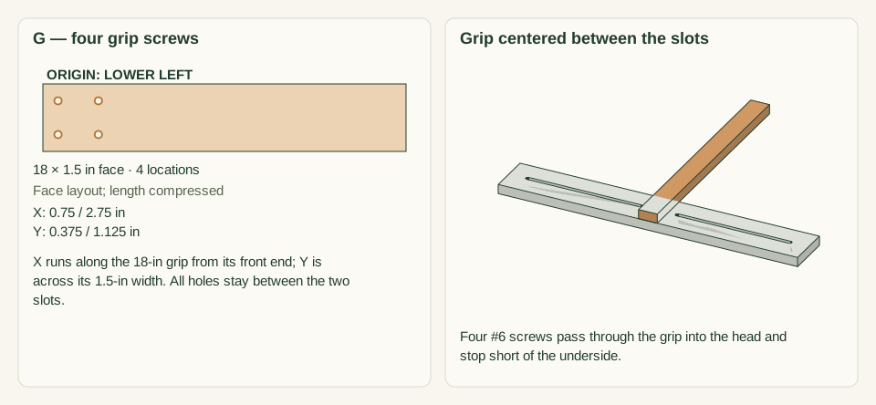
Place the grip at x 11.25–12.75 and y 0–18 on top of the head, measuring from the head front-left corner. Clamp the overlap. Mark four screw centers at x 11.625 and 12.375, each at y 0.75 and 2.75. Drill clearance through the grip only and pilots into the head. Fit four #6 × 1.25-inch screws flush, leaving 0.5 inch of nominal bite.
Close-up · Whole model shows the complete part
Loading the 3D view…
Drag to turn. Pinch or use + / − to zoom. The written step covers workholding and tool use.
Scroll or swipe the enlarged drawing to read its dimensions. Choose Fit to see the whole drawing again.
Fasten the central grip to the slotted head before installing the two adjustable feet.
Check: All four screws avoid the slots and stop 0.25 inch above the head underside.
- 07
Assemble the captive markers
Pass each bolt through its wooden foot and then the appropriate head slot. Add a washer and wingnut above the head. Keep the foot below and fit any needed smooth thread-end cover without obstructing adjustment.
Close-up · Whole model shows the complete part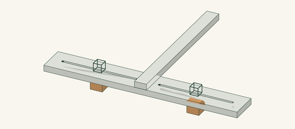
Loading the 3D view…
Drag to turn. Pinch or use + / − to zoom. The written step covers workholding and tool use.
Scroll or swipe the enlarged drawing to read its dimensions. Choose Fit to see the whole drawing again.
Add the wooden feet below the slots and the actual washers and wing nuts above. The thin upper boxes are clearance references.
Check: Both feet remain captive while loose enough to slide for setting.
- 08
Set centers and tighten by hand
Measure between foot/bolt centers from the same rule. Position both feet square to the head and tighten wingnuts by hand. Do not crush the wood or use pliers to force an unsuitable washer or nut.
Close-up · Whole model shows the complete part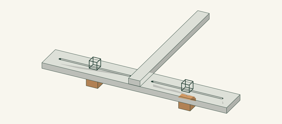
Loading the 3D view…
Drag to turn. Pinch or use + / − to zoom. The written step covers workholding and tool use.
Scroll or swipe the enlarged drawing to read its dimensions. Choose Fit to see the whole drawing again.
Set both foot centers from the same rule and tighten by hand. Recheck the actual crop-selected spacing instead of copying the example.
Check: Center-to-center spacing matches the selected crop setting and neither foot rotates freely.
- 09
Trial shallow parallel marks
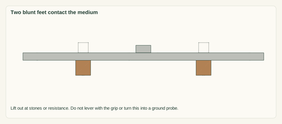
On prepared practice medium, lower both wooden feet gently and pull a short straight line using the grip. Check the two row marks against a rule. Stop if the feet slip, the head twists or force is required.
Close-up · Whole model shows the complete part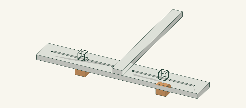
Loading the 3D view…
Drag to turn. Pinch or use + / − to zoom. The written step covers workholding and tool use.
Scroll or swipe the enlarged drawing to read its dimensions. Choose Fit to see the whole drawing again.
Make shallow trial marks in known prepared medium. The broad wooden feet are markers, not digging tines.
Check: Two shallow parallel marks repeat the intended center spacing.
- 10
Mark, clean and release
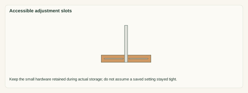
Use only on the cleared growing surface, then remove the tool immediately. Brush out slots, dry wood and store with small hardware retained. Recheck spacing at every reuse rather than assuming wingnuts stayed fixed.
Close-up · Whole model shows the complete partLoading the 3D view…
Drag to turn. Pinch or use + / − to zoom. The written step covers workholding and tool use.
Scroll or swipe the enlarged drawing to read its dimensions. Choose Fit to see the whole drawing again.
Clean the two slots and recheck the setting before reuse. Hardware and feet are omitted in this inspection view to expose the openings.
Check: The tool has no sharp tines, loose parts or unverified saved spacing.


05 / Keep it sound
Care
After the build
- The markers only make shallow reference lines. Prepare soil by the appropriate separate method rather than forcing this tool into a hard bed.
- No row-spacing or sowing-depth recommendation is supplied by the slot geometry.
Check it each season
- Inspect connections and hand-contact edges before use. Unload before tightening or replacing parts; replace a cracked member rather than adding a screw beside the crack.
- Brush off debris, wipe only as needed and dry with air around the joints. Store dry when the item is not in use.
If something looks wrong
- Foot rotates or slides
- Stop and inspect washer contact, slot damage and hand-tightened fit before continuing.
- Marks diverge
- Check the head is held square and that both feet remain at the same orientation.
- Slot cracks at an end
- Replace the head rather than extending the slot into a weakened end web.
- Tool catches a stone
- Lift it out and resolve the prepared surface; do not pry or add metal spikes.
Keep exploring